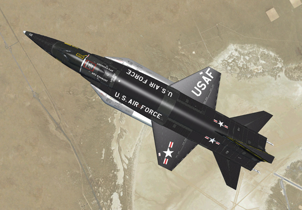
Top view of the aerodynamic control surfaces (X-15A-2 SE).
The X-15 aerodynamic flight control system incorporates hydraulically actuated yaw and pitch-roll control surfaces. The irreversible characteristics of the hydraulic system hold the control surfaces against any forces that do not originate from pilot control movement and prevent these forces from being transmitted back to the pilot controls. Thus, aerodynamic loads of any kind cannot reach the pilot through the controls.
An artificial-feel system is built into the control system to simulate feel at the pilot controls. In-flight trimming in pitch is accomplished by changing the neutral (no-load) position of the artificial-feel system and repositioning the control sticks.
Yaw control is provided by movable upper [4, fig. 3-1] and ventral vertical stabilizers [17, fig. 3-2].
The left and right horizontal stabilizers [1, fig. 3-1] provide pitch and roll control, simultaneous operation for pitch control, and differential operation for roll control. An assist to the aerodynamic damping in pitch, roll, and yaw is provided by a stability augmentation system (SAS).
When both hydraulic systems fail, the aerodynamic control surfaces will remain in the position at which failure occurred. However, the surfaces may be moved in the direction in which they are driven by aerodynamic loads by repositioning of the pilot controls in the direction to streamline the surface.
The pedals [11, fig. 4-1], center stick [8, fig. 4-1], and console stick [3, fig. 5-5] are mechanically linked to the control valves on their respective actuators. Movement of a pilot control results in corresponding movement of its actuator control valve. As the actuator moves, the control valve is repositioned to a neutral position so that flow to the actuator is shut off. The pressure remaining in the actuator serves to hold the control surface in the desired position. Control cable rig tension is maintained throughout a wide temperature and deflection range by thermal expansion and contraction tension regulators.
The artificial-feel system ("force feedback" in the simulator) gives a sense of control feel to the pilot under all flight conditions where the aerodynamic controls are used. Aerodynamic stick [8, fig. 4-1] and rudder pedals [11, fig. 4-1] forces are simulated by spring-loaded bungees in the control system. The bungees apply loads to the pilot controls in proportion to stick or pedal movement, but the resultant feel has no relation to actual air loads.
A nonlinear stick-to-stabilizer displacement ratio is incorporated in the pitch control linkage to minimize sensitivity. Pitch trim is obtained by shifting the neutral "no-load" position of the feel bungee to a stick position corresponding to the desired horizontal stabilizer position.
Roll and yaw trim is adjustable only on the ground to compensate for airplane asymmetrical conditions.
The horizontal stabilizer [1, fig. 3-1] consists of two all-movable, one-piece surfaces which can be moved simultaneously, differentially, or in compound.
Aerodynamic control in pitch is obtained by simultaneous displacement of the left and right stabilizer surfaces. Roll control is obtained by differential displacement of the stabilizer surfaces. Combined pitch-roll control is obtained by compound movement of the stabilizer surfaces.
A series of mixer bell cranks sum pilot control and SAS inputs to the two stabilizer actuator valves to obtain the desired pitch or roll-pitch control surface displacement.
Aerodynamic control in yaw mode is obtained through displacement of the upper [4, fig. 3-1] and ventral vertical stabilizers [17, fig. 3-2], which are actuated simultaneously through the coupled linkage between the upper and ventral vertical stabilizer actuator valves. Pilot pedal [11, fig. 4-1] displacement and SAS yaw inputs are transmitted by mechanical linkage and cables to the synchronized upper and ventral stabilizer control valves.
Since the ventral extends below the main landing skids, it must be jettisoned before landing. Four explosive bolts and a piston containing an explosive charge are electrically fired when the ventral jettison button [67, fig. 5-1] is depressed. If this is not done, or if the ventral fails to jettison when the button is depressed, the ventral will jettison automatically when the landing gear is lowered. For either method of jettisoning, however, the ventral arming switch [35, fig. 5-1] must be at ARM, to arm the jettison circuits.
Note: In the simulation, the ventral is "invisible" when the aircraft sits on the ground. It appears when the aircraft is airborne (if not jettisoned).
In this section:
Aerodynamic Flight Controls and Indicators