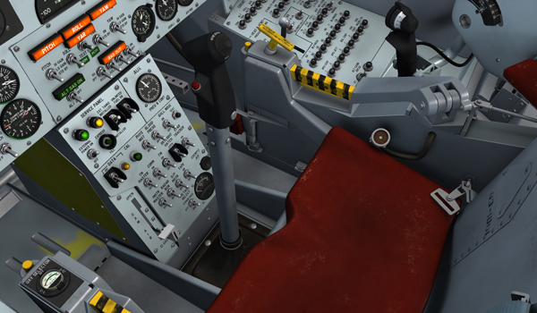
Center stick, right console stick and rudder pedals in the virtual cockpit of the X-15A-2 SE.
The center stick [8, fig. 4-1] is designed for use during normal periods of longitudinal and vertical acceleration. Pilot pitch and roll inputs to the center stick are summed by the mixer bell cranks and applied to the horizontal stabilizer actuator valves. A microphone button and alternate trim switch are on the stick grip. The button is in parallel with the microphone button on the console stick [3, fig. 5-5].
Clicking the stick handle in the virtual cockpit disables the ballistic control stick [8, fig. 5-4] and enables the center stick and the right console stick [3, fig. 5-5]. The center stick is enabled by default.
Clicking the microphone button will open the ATC window in the simulator.
The center stick can be made invisible by clicking the center stick boot [9, fig. 4-1]. This gives the pilot a better view of the center pedestal, making the switches and controls more accessible. Click again to show the center stick.
The console stick [3, fig. 5-5], on the right console, enables the pilot to control the airplane throughout the periods of high longitudinal and vertical accelerations. This stick has full range of surface control in pitch and roll and is coupled to the center stick linkage through separate pitch and roll hydraulic boost actuators to reduce console stick pilot control forces and to synchronize displacement of the center and console sticks.
The console stick has a pitch trim knob and a microphone button. The trim knob is graduated in degrees. When the trim control switch [1, fig. 5-4] is in NORMAL, moving the trim knob causes corresponding movement of the pitch trim actuator. A microphone button on the console stick is in parallel with the microphone button on the center stick [8, fig. 4-1].
The console stick movements are synchronized with the center stick. Clicking the console stick handle disables the ballistic control stick [8, fig. 5-4] and enables the console stick and the center stick. The console stick is enabled by default.
Clicking the microphone button will open the ATC window in the simulator.
Conventional rudder pedals [11, fig. 4-1], which are adjustable, are mechanically linked to the yaw system mixer bell crank. Pedal movement and SAS inputs are summed by a mixer bell crank, which in turn transmits the summed signal mechanically to the stabilizer actuator control valves.
This two-position switch [1, fig. 5-4], on the left side of the cockpit, controls selection of normal or alternate trim.
With the switch at the maintained NORMAL position, the center stick [8, fig. 4-1] trim control knob is inoperative and primary AC and DC power is applied to the electronic trim amplifier and relay unit to activate the console stick pitch trim knob [4, fig. 5-5]. Movement of the pitch trim knob on the console stick then causes primary DC power to be applied to the pitch trim actuator.
With the trim control switch at the maintained ALTERNATE position, output of the electronic trim amplifier is cut off, the pitch trim knob is inoperative, and pitch trim is accomplished through the alternate trim switch on the center control stick.
This three-position switch (top hat) on the center stick [8, fig. 4-1] controls primary DC bus power to the pitch trim actuator. The switch is spring-loaded to the center position, and all positions are unmarked.
With the switch in the center position and the trim control switch [1, fig. 5-4] at NORMAL, primary DC bus power is applied to the electronic trim amplifier and relays, and pitch trim is accomplished by movement of the console stick pitch trim knob [4, fig. 5-5]. Moving the alternate trim switch forward (NOSE DOWN) or aft (NOSE UP) bypasses the electronic trim amplifier and applied primary DC bus power directly to the pitch trim actuator, causing the actuator to move for nose down or nose up trim, as selected.
If the trim control switch is moved from ALTERNATE to NORMAL, the pitch trim actuator will run to the preset position of the console stick pitch trim knob.
This guarded, two-position switch [35, fig. 5-1] is on the instrument panel right hand wing and is labeled "VENTRAL JETT".
With the switch at DE-ARM, the circuit which controls primary DC bus power to the explosive bolts and explosive charge in the ventral [17, fig. 3-2] (or dummy ramjet [18, fig. 3-2]) jettison piston is interrupted and the ventral (or ramjet) cannot be jettisoned either selectively through the ventral jettison button [67, fig. 5-1] or automatically when the landing gear is lowered. With the switch at ARM, the ventral (or ramjet) jettison circuit is armed.
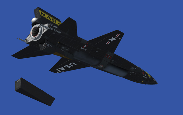
Ventral jettison.
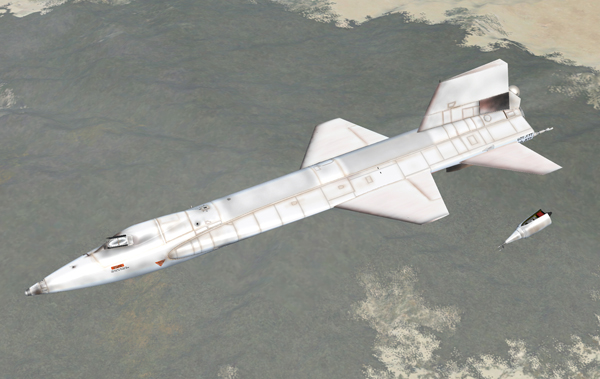
Ramjet jettison.
This jettison button [67, fig. 5-1], labeled "VENTRAL JETT", is recessed within a circular guard on the instrument panel left wing. The button is powered by the primary DC bus and is the primary means of jettisoning the ventral [17, fig. 3-2] (or dummy ramjet [18, fig. 3-2]).
When the button is depressed, with the ventral arming switch [35, fig. 5-1] at ARM, four explosive-type bolts and a piston containing an explosive cartridge are fired. At the instant the bolts separate, the piston is driven downward to forcibly jettison the ventral (or ramjet).
Refer to "Hydraulic Power Supply Systems".