
An engine fire can be programmed in the simulator to practice emergency procedures.
A detection circuit is provided to detect and indicate a fire condition in the engine compartment. This circuit is of the continuous-element type, which detects excessive temperatures anywhere along its length. The system is powered by the battery bus and continuously monitors the resistance of the circuit.
The resistance of the material used in the circuit varies inversely with temperature and total length of the sensing circuit. Whenever temperatures in the engine compartment reach 1100°F (594 °C) or higher, the resistance of the sensing element falls below a preset value because of the excessive temperature, and the warning system is energized.
A placard-type warning light, a system selector switch, and a test switch are in the cockpit (see below).
For emergency procedures in case of a fire-warning indication, refer to "Fire or Explosion" in the Emergency Procedures section.
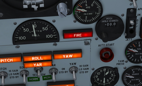
Fire-warning light.
An abnormal rise in engine compartment temperature is shown by a placard-type warning light [47, figure 5-1], on the instrument panel. The light is powered by the primary DC bus and has a red plastic cap which shows the word "FIRE" when the light is on. The light may be tested by a push-to-test switch [37, fig. 5-1] on the instrument panel right wing.
A fire-warning light and detection circuit test button [37, fig. 5-1] is on the instrument panel right wing. The button is powered by the primary DC bus. When the button is pressed, the fire-warning light [47, figure 5-1] should come on, verifying the continuity of the detection circuit.
See also:
Engine Compartment Purging System