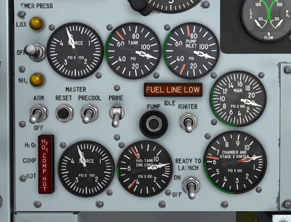
Helium (source) system gauges on the lower left section of the main instrument panel.
Helium to pressurize the turbopump hydrogen peroxide supply tank and to supply pneumatic pressure for engine and propellant control is contained in four spherical tanks.
One tank is between the liquid oxygen and ammonia tanks. Two tanks are in the left and right wing root fairing tunnels outboard of the engine. These three tanks are interconnected, supplying 3600 psi pressure to two pressure-reducing regulators in parallel.
The fourth tank is just to the right of the turbopump H2O2 supply tank and supplies helium at 3600 psi to a single pressure-reducing regulator for emergency or secondary pneumatic control of the propellant jettison valves. This tank is interconnected with the other three tanks for filling purposes only.
From the parallel pressure-reducing regulators of the main supply, helium at 575 to 600 psi is supplied to the engine helium manifold for operation of engine control valves, to the turbopump H2O2 supply tank for tank pressurization, and to propellant control jettison and main feed valves.
Two of the tanks supply helium directly to the helium dump valve, for engine compartment purging. The dump valve is solenoid-operated and controlled by the helium release selector switch [1, fig. 5-1]. For information on operation of this switch, refer to "Helium Release Selector Switch" below.
The helium to the engine helium manifold is in turn routed to a control gas valve and the two gas regulators in the purge valve network at a pressure of 550 to 600 psi. The control gas valve is energized during the prime period and admits helium at a pressure of 550 to 600 psi to the pilot valves for the prime valve, first-stage igniter start valve, second-stage igniter start and shutoff valves, and main propellant valve.
Helium at a pressure of 125 to 200 psi is routed from the two purge gas regulators and to the return side of the second-stage igniter start and shutoff valves. Another regulator supplies helium from the helium manifold at 7.5 psi to the lubrication system accumulator, engine control box, and hydraulic power package.
Refer to "Engine Compartment Purging System".
A dual-indicating H2O2 source and purge pressure gauge [57, fig. 5-1], on the instrument panel, is powered by the 26-volt AC bus. This gauge indicates the helium pressure available from three of the engine and propellant helium system tanks.
Needle 1 indicates pressure in the large tank between the liquid oxygen and ammonia tanks. Needle 2 indicates pressure in the two smaller tanks in the wing root fairing tunnels.
The gauge is calibrated from 0 to 4000 psi in increments of 100 psi. Normally, the two pointers will indicate the same pressure. However, if there is a malfunction of the emergency jettison system helium supply or if helium is dumped into the engine compartment, the pointers will not indicate the same pressure. There is no gauge in the cockpit which indicates pressure in the emergency jettison system helium supply tank.
Note: This gauge is modified in the X-15A-2 airplane. Refer to "X-15A-2 Propellant Supply System for details.
This dual-indicating gauge [55, fig. 5-1], on the instrument panel, is powered by the 26-volt AC bus.
One pointer, labeled "C", indicates engine control line (helium) pressure downstream of the two parallel pressure regulators. The other pointer, labeled "T", indicates pressure in the turbopump H2O2 supply tank.
The gauge is calibrated from 0 to 1000 psi in increments of 50 psi, except that the range 0 to 100 is in increments of 20 psi.
In this section:
Propellant Pressurization Helium System
Propellant Emergency Pressurization System
X-15A-2 Propellant Supply System