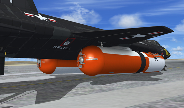
External drop tanks installed on the X-15A-2 SE addon.
The real airplane has provisions for carrying liquid hydrogen (LH2).
Note: Liquid hydrogen is not used on the X-15A-2 addon.
Helium to pressurize the turbopump hydrogen peroxide supply tank and to supply pneumatic pressure for engine and propellant control is contained in three spherical tanks pressurized to 3600 psi. A 2.0-cubic foot bottle is in the nose section of the left external tank, and 3.54-cubic-foot and 0.491-cubic-foot bottles are in the 29-inch fuselage extension area.
Initial helium pressure is supplied by the 3.54-cubic-foot bottle; however, when engine chamber pressure reaches approximately 150 psi (igniter idle phase), the 3.54-cubic-foot bottle is disconnected from the system, and pressure is supplied by the 2.0-cubic foot bottle in the external tank. When the external tanks are released, the 3.54-cubic-foot bottle is reconnected to the system and supplies the required helium pressure.
The 0.491-cubic-foot bottle provides engine compartment purge gas or provides an auxiliary gas source when the auxiliary liquid hydrogen system is attached.
In addition to the helium supply contained in the airplane, two 3.3-cubic-foot bottles are in the nose section of the left external tank. These bottles are pressurized to 3600 psi and are manifolded into the helium propellant supply system to the two propellant system regulators.
With the vent, pressurization, and jettison lever [11, fig. 5-4] at either PRESSURIZE or JETTISON and the fuel selector switch [8, fig. 5-6] at EXTERNAL, helium pressure flows from the two 3.3-cubic-foot bottles, through the regulators to the liquid oxygen and ammonia external tanks. Pressure builds up in the external tanks, forcing the propellants to flow through the transfer system to the respective internal tanks. The regulators sense the resultant pressure build-up in the internal tanks and regulate the helium flow as required to maintain a nominal 48 psi pressure at the regulator discharge port. Helium pressure is diverted from the internal tanks and directed to the external tanks by helium solenoid valves.
When the fuel selector switch is placed at INTERNAL, the propellant transfer system is deactivated at external tanks empty, or the external tanks are released full, these solenoid valves are de-energized, and the helium pressure is directed to the internal tanks without a noticeable loss in gas flow rate.
On the real aircraft, helium for pressurization of the liquid hydrogen system is supplied by a 2.4-cubic-foot bottle [11, fig. 3-2] located on top of the engine shroud, just aft of the upper vertical tail. This gas source also provides engine compartment purge when the LH2 is attached.
Note: Liquid hydrogen is not used in the X-15A-2 addon.
Helium pressure contained in the 0.491-cubic-foot bottle is displayed on the "AUX PNEU & CONT." gauge [21, fig. 5-3], on the center pedestal. The gauge is calibrated in 100 psi increments from 0 to 4000 psi. The gauge is powered by the primary DC bus.
Helium pressure contained in the airplane 3.54-cubic foot bottle and the 2.0-cubic-foot bottle in the left external tank is displayed on a dual-reading gauge [57, fig. 5-1], on the instrument panel. Two pointers, one labeled "I" for the 3.4-cubic-foot bottle and one labeled "E" for the 2.0-cubic-foot bottle, travel over a common arc of calibrations. The arc is calibrated in 100 psi increments from 0 to 4000 psi. The gauge is powered by the 26-volt AC bus.
Helium pressure contained in the airplane 7.1-cubic foot bottle and the two 3.3-cubic-foot bottles in the left external tank is displayed on a dual reading gauge [69, fig. 5-1], on the instrument panel. Two pointers, one labeled "I" for the 7.1-cubic-foot bottle and one labeled "E" for the two 3.3-cubic-foot bottles, travel over a common arc of calibrations. The arc is calibrated in 100 psi increments from 0 to 4000 psi. The gauge is powered by the 26-volt AC bus.
See also: