The throttle [12, fig. 5-4] controls thrust output of the engine. The throttle quadrant has three marked positions: OFF, 50%, and 100%.
The throttle controls an electromechanical servo system, which includes a synchro transmitter attached to the throttle, a servo amplifier, and an actuator position transmitting synchro linked to the turbopump governor.
Turbopump and first and second-stage igniter operation is accomplished with the throttle at OFF (full aft and outboard). During the 30-second idle operation period with the throttle at OFF, the turbopump is automatically maintained at idle speed.
Within 30 seconds after igniter idle operation is begun, the throttle must be moved to START (50%) to open the main propellant valves to the main thrust chamber or the start sequence must be terminated. After main thrust chamber operation is begun, movement of the throttle between 50% and 100% will vary engine thrust accordingly.
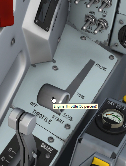
Engine throttle on the left console.
To start the engine after the normal ignition sequence procedures are performed, simply left-click the white throttle handle to move the throttle inboard to START (50%). This will ignite the main thrust chamber.
Drag the handle to the desired level of thrust during normal engine operation. The throttle can also be controlled with the keyboard and/or the joystick.
To shut down the engine, simply move the throttle aft to 50% then right-click the white handle to shut off the engine and move the throttle outboard back to its OFF position.
Note: The throttle will not move if not left-clicked first.
This lever [11, fig. 5-4] controls the pressurization system selector valve. The valve is a manually controlled pneumatic selector valve.
The lever has three positions: VENT, PRESSURIZE, and JETTISON. Simply drag the white lever to the desired position.
With the lever at VENT, helium pressure (from the helium pressure control system) is applied to all tank control valves in the propellant system. The pressurization valves close and the vent valves open, venting the H2O2, liquid oxygen, and ammonia tanks.
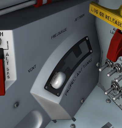
Vent, pressurization, and jettison lever on the left white control box.
In order to obtain engine operation, the lever must be moved to PRESSURIZE, opening the propellant system pressurization valves and closing the vent valves. This allows helium to enter and pressurize the turbopump H2O2 supply tank and the liquid oxygen and ammonia tanks.
When the lever is positioned to JETTISON, helium pressure is applied to open three jettison valves and pressurize the H2O2, liquid oxygen, and ammonia tanks. The three propellants will then begin to dump overboard [5, 8 and 10, fig. 3-2].
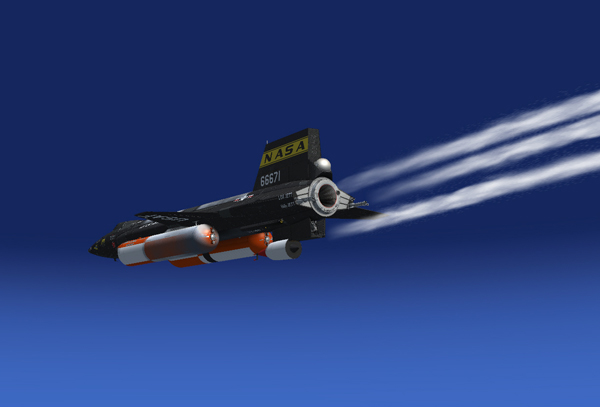
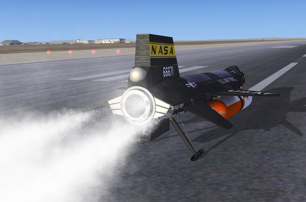
Propellant jettison.
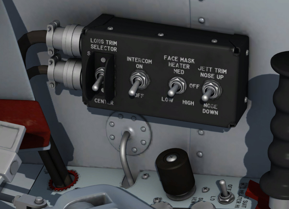
Jettison trim switch on the control box, on the left vertical side panel.
This switch [4, fig. 5-4] is on the left vertical side panel. It has three positions: NOSE UP, NOSE DOWN, and an unmarked, center off position. The switch is powered by the 28-volt primary DC bus.
With the vent, pressurization, and jettison control lever [11, fig. 5-4] at JETTISON, the jettison stop switches [59, FIG. 5-1] in the JETT position, and this switch at the unmarked off position, simultaneous jettisoning of H2O2, liquid oxygen, and ammonia will occur.
Moving this switch to NOSE UP (when nose-down trim is felt) stops the flow of the ammonia.
Moving the switch to NOSE DOWN (when nose-up trim is felt) stops the flow of liquid oxygen.
In either case, when the airplane returns to trim, the switch must be released and allowed to return to the unmarked off position.
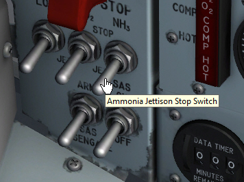
Jettison stop switches on the main instrument panel left wing.
Three jettison stop switches [59, fig. 5-1], on the instrument panel left wing, have a STOP and a JETT position. These switches, powered by the primary DC bus, are normally left in the STOP position until the prelaunch cruise portion of the flight.
To perform a test of the turbopump H2O2, liquid oxygen, and ammonia jettison system, the vent, pressurization, and jettison control lever [11, fig. 5-4] should be placed at JETTISON. The systems then can be tested by placing the switches to JETT.
The jettison line of each system should then emit a vaporous cloud. Flow will cease when the switches are returned to the STOP position or when the vent, pressurization and jettison control lever is moved to PRESSURIZE.
See figure 3-2 for location of jettison, drain, and bleed outlets.
The engine master switch [63, fig. 5-1], on the instrument panel, is powered by the primary DC bus. With the switch at OFF, primary DC bus power for engine control and engine indicator lights is interrupted. With the switch at ARM, primary DC bus power is applied to the engine indicator lights and engine control switching units.
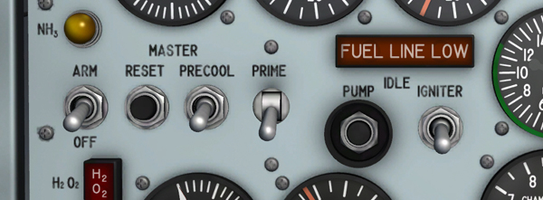
Engine controls on the main instrument panel.
The engine reset button [62, fig. 5-1], on the instrument panel, is powered by the primary DC bus through the engine master switch [63, fig. 5-1]. For a normal engine start or if a malfunction causes automatic shutdown during any phase of operation, depressing this button positions the engine control circuits to the armed position. However, if the malfunction which caused shutdown persists, engine control circuits will not be armed.
The engine precool switch [61, fig. 5-1], on the instrument panel, is powered by the primary DC bus through the engine master switch [63, fig. 5-1]. It has two maintained positions: PRECOOL and OFF (down). With an engine start sequence initiated, moving the switch to PRECOOL opens the liquid oxygen main feed valve and precools the system up to the main propellant valve. The precooling flow dumps overboard through the engine liquid oxygen prime valve [4, fig. 3-2].
Note: About 10 minutes is required to precool the engine liquid oxygen system. After precooling is completed, the engine can be maintained in a precooled condition for an extended period by the following schedule: engine precool switch at OFF for 20 minutes, then at PRECOOL for 7½ minutes, repeating this cycle as often as necessary.
Engine precool and prime.
The engine prime switch [56, fig. 5-1], on the instrument panel, has three positions: an unmarked, maintained center position; a momentary up PRIME position; and a maintained down STOP PRIME position. It is powered by the primary DC bus.
With an engine start sequence initiated, moving the switch momentarily to PRIME opens the liquid oxygen and ammonia main feed valves and the turbopump H2O2 upstream safety valve and admits helium to the engine control and purge systems. Approximately 30 seconds is required for priming at high-flow rate, and when the engine precool switch [61, fig. 5-1] is placed at OFF, prime continues at low-flow rate until an actual start stops the prime or until the engine prime switch is placed momentarily at STOP PRIME.
The priming flow dumps overboard through the engine liquid oxygen and ammonia prime valves [4 and 9, fig. 3-2].
Engine operation may be terminated during any phase by moving this switch to STOP PRIME.
The turbopump idle button [54, fig. 5-1], on the instrument panel, is powered by the primary DC bus through the engine master switch [63, fig. 5-1] and the engine reset button [62, fig. 5-1].
With an engine start sequence initiated and the prime phase completed, depressing this button for one second opens the turbopump H2O2 downstream shutoff valve, which starts turbopump operation. When pressure of the ammonia in the propellant manifold builds to approximately 210 psi, the turbopump speed control system begins operation and maintains the turbopump at idle speed.
Turbopump exhaust gas can be seen at the back of the airplane when the turbopump is operating [2, fig. 3-2].
This switch [53, fig. 5-1], on the instrument panel, receives power from the primary DC bus through the engine master switch [63, fig. 5-1] and the engine reset button [62, fig. 5-1].
With an engine start sequence initiated and the engine turbopump operating at idle speed, moving this switch from OFF (down) to IGNITER (up) causes the following sequence of actions:
Note: The igniter-idle switch, in the virtual cockpit, cannot be set if the engine turbopump is not running.
In this section:
Automatic Ignition Sequence Start Button
See also: