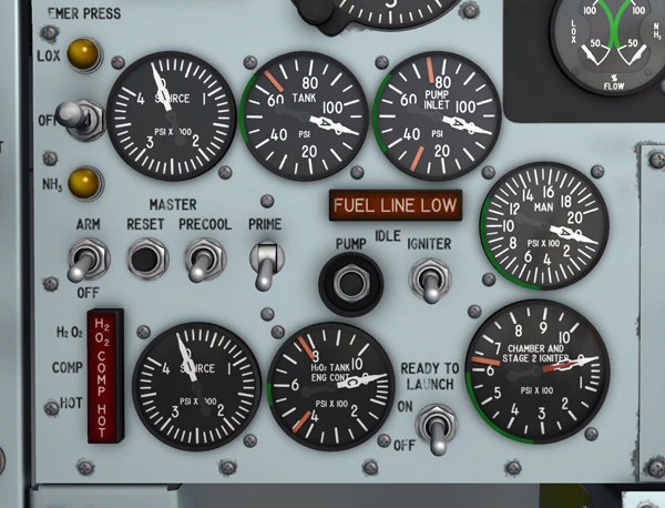
Engine indicators and gauges on the lower left section of the main instrument panel.
This dual-indicating gauge [71, fig. 5-1], on the instrument panel, is powered by the 26-volt AC bus.
The gauge indicates the two propellant tank pressures. The gauge is graduated from 0 to 100 psi in increments of 5 psi. One pointer of the gauge has the letter "L", indicating the liquid oxygen tank pressure; the other pointer has the letter "A", indicating the ammonia tank pressure.
This dual-indicating gauge [72, fig. 5-1] is powered by the 26-volt AC bus.
It indicates liquid oxygen and ammonia pressures at the engine turbopump inlets. This gage is graduated from 0 to 100 psi in increments of 25 psi. The pointer labeled "L" reads the liquid oxygen pressure; the pointer labeled "A" indicates the ammonia pressure.
This dual-indicating gauge [51, fig. 5-1], on the instrument panel, is powered by the 26-volt AC bus.
The gauge indicates propellant pump discharge pressures. It is graduated from 0 to 2000 psi in increments of 50 psi. One pointer is labeled "L" and indicates liquid oxygen pump discharge pressure; the other pointer is labeled "A" and indicates ammonia pump discharge pressure.
This dual-indicating gauge [50, fig. 5-1], on the instrument panel, is powered by the 26-volt AC bus. The gauge is graduated from 0 to 1000 psi in increments of 20 psi from 0 to 100, and 50 psi from 100 to 1000. The short (red) hand indicates pressure in the second-stage igniter. The long (white) hand indicates pressure in the main thrust chamber.
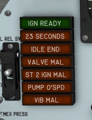
Engine indicators.
This green indicator light [2a, fig. 5-1], on the instrument panel, is powered by the primary DC bus through the engine master switch [63, fig. 5-1].
When illuminated, it reads "IGN READY", indicating that the engine electrical circuits and purge gas network have been energized. In the normal starting sequence, this light will go out for 2 seconds when the igniter-idle switch [53, fig. 5-1] is moved to IGNITER, then come on again. During all helium purges, this light will go out. This light may be tested by the indicator, caution, and warning light test circuit.
This amber caution light [2b, fig. 5-1] on the instrument panel, is powered by the primary DC bus through the engine master switch [63, fig. 5-1].
During a normal engine start sequence, this light will come on when 23 seconds of mated igniter idle operation has occurred. Illumination of the light indicates that a major portion of the nitrogen cooling gas has been used and that launch should be accomplished as soon as possible. The light, when illuminated, reads "23 SECONDS" and serves to warn the pilot to terminate igniter idle operation or to continue on to the launch phase. This light may be tested by the indicator, caution, and warning light test circuit.
This amber caution light [2c, fig. 5-1], on the instrument panel, is powered by the primary DC bus through the engine master switch [63, fig. 5-1].
This light will illuminate, reading "IDLE END", when the 30-second igniter idle phase of engine operation is complete. When this light comes on, engine shutdown must be accomplished or operation continued into the main chamber phase (after launch). This light may be tested by the indicator, caution, and warning light test circuit.
This amber caution light [2d, fig. 5-1], on the instrument panel, is powered by the primary DC bus through the engine master switch [63, fig. 5-1].
When illuminated, this light reads "VALVE MAL". This light will come on when malfunction shutdown occurs because the main or first stage propellant valve is improperly positioned during the starting sequence. The light will also come on momentarily whenever a malfunction shutdown occurs with the main chamber operating. This light may be tested by the indicator, caution, and warning light test circuit.
This amber caution light [2e, fig. 5-1], on the instrument panel, is powered by the primary DC bus through the engine master switch [63, fig. 5-1].
When illuminated, this light reads "ST 2 IGN MAL". The light will come on when a malfunction shutdown occurs during the starting sequence because of failure of the second-stage igniter to reach operating pressure. The light will also come on momentarily whenever a malfunction shutdown occurs with the main chamber operating. This light may be tested by the indicator, caution, and warning light test circuit.
This amber light [2f, fig. 5-1], on the instrument panel, is powered by the primary DC bus through the engine master switch [63, fig. 5-1].
When illuminated, this light reads "VIB MAL". The light comes on when the engine shuts down because of excessive vibration. Excessive engine vibration causes a shutdown signal to be transmitted from either of two sensors to the engine control box. The signal causes the actuation of two malfunction relays in the control box that de-energize the prime, precool, and firing circuits to shut down the engine and turn on the light. If the light comes on during powered flight, an engine restart may be attempted. This light may be tested by the indicator, caution, and warning light test circuit.
This amber caution light [2g, fig. 5-1], on the instrument panel, is powered by the primary DC bus through the engine master switch [63, fig. 5-1].
When illuminated, this light reads "PUMP O'SPD." The light will come on if a malfunction shutdown occurs because of turbopump overspeed which is not corrected by the turbopump governor. This light may be tested by the indicator, caution, and warning light test circuit.
An amber "FUEL LINE LOW" caution light [64, fig. 5-1] is on the left side of the instrument panel. This light, powered by the primary DC bus through the engine master switch [63, fig. 5-1], is actuated by a pressure switch installed in the fuel (ammonia) line downstream of the main safety valve.
If fuel pressure at the turbopump inlet drops to 32 (±2) psi, the light will come on. Illumination of the light indicates that partial cavitation of the pump is likely to occur.
When the "FUEL LINE LOW" caution light is on, there is not sufficient cooling around the main chamber of the engine for temperature protection. Thrust settings above 50% may increase the temperature and cause damage to the engine.
If the light comes on before the engine is started, the start will be aborted. When this light has been illuminated, it will remain on until the engine master switch has been placed in the OFF position. The light may be tested by the indicator, caution, and warning light test circuit.
Refer to "Fuel Line Pressure Low" in the Emergency Procedures section.
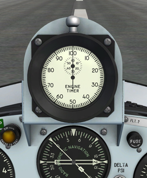
Engine timer.
A special mechanical analog stopwatch [11, fig. 5-1] is installed on top of the main panel for measuring engine burn time. The timer will start automatically upon ignition of the main thrust chamber and will stop when the engine is shut down. A reset button is provided on top of the timer.
The user can select whether the engine timer is installed or not. This feature may be helpful during landing, especially if the canopy is made invisible. To remove the engine timer, click the white label [75, figure 5-1] located to the right side of the timer, on the main instrument panel. Click again to re-install the timer.
See also: