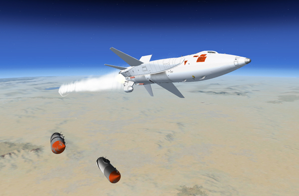
External tanks are being jettisoned from the X-15A-2 SE.
A jettisonable external tank may be mounted on the lower left and lower right side fairings.
The right-hand external tank has a usable capacity of 1053 gallons (6070 pounds) of liquid anhydrous ammonia. The left-hand external tank has a usable capacity of 770 gallons (7590 pounds) of liquid oxygen. The left-hand tank also contains three small cylindrical helium tanks for propellant pressurization and airplane pneumatic control.
Each external tank has a self-contained jettison-recovery system. The parachute recovery portion of the system is automatically activated when the tanks leave the airplane.
Servicing of the external tanks is accomplished, after the tanks are installed on the airplane, through the airplane internal propellant system. In flight, the liquid oxygen and ammonia are transferred under helium pressure to their respective internal tanks. Indication of propellant flow from the external tanks is displayed to the pilot on a gauge in the cockpit.
When the external tanks are empty, the system shifts automatically to the internal tanks. Empty, full or partially-full external tanks can be released automatically or manually, as selected by the pilot. Lights in the cockpit indicate when the external tanks are ready to be jettisoned.
A fictitious external tanks option switch [26, fig. 5-3], on the service panel, is provided for choosing whether or not the X-15A-2 external drop tanks are installed. The external tanks provide an additional 1053 gallons of anhydrous ammonia and 770 gallons of liquid oxygen which corresponds approximately to an additional 60 seconds of engine burn time.
Make sure this switch is set to INSTALLED for true X-15A-2 operation (external tanks on).
The external tanks option switch cannot be set if the propellant tanks are pressurized (vent, pressurize, and jettison lever [11, fig. 5-4] not at VENT).
Note: External tanks are emptied when the external tanks option switch is moved to NOT INSTALLED, then back to INSTALLED. Tanks will need to be refilled (refer to "Express Fill Button").
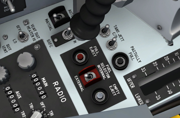
Drop tank controls are on the left console.
The two-position "FUEL SELECTOR" switch [8, fig. 5-6], on the drop tanks control panel (on the left console), is powered by the primary DC bus.
With the switch at EXTERNAL (propellant system pressurized), the transfer system is activated and the propellant is transferred from the external tanks to the internal tanks. At the end of a preset time period, an intervalometer times out, deactivating the transfer system, and indicator lights in the cockpit come on, indicating that the tanks are ready to be released. The propellant feed system automatically shifts to internal tank feed, and it is not necessary to reposition the "FUEL SELECTOR" switch.
When the switch is placed at INTERNAL (propellant system pressurized), the transfer system is deactivated and propellant feeds from internal tanks only, regardless of propellant remaining in the external tanks.
Note: The "FUEL SELECT" switch must be in the EXTERNAL position whenever external tanks are installed.
Note: To pressurize or jettison the propellant in the external tanks, the fuel selector switch must be at EXTERNAL, when the desired function is selected with the vent, pressurization, and jettison lever [11, fig. 5-4]. The external tanks are vented, regardless of the position of the fuel selector switch, when the vent, pressurization, and jettison lever is moved to VENT.
These two-position switches [1-2, fig. 5-6], labeled "TANK JETT C/B", on the drop tanks control panel [18, fig. 4-1] (on the left console), apply or remove battery bus power to the external tank release circuits and controls.
This two-position, guarded switch [4, fig. 5-6], on the drop tanks control panel (on the left console), is powered by the battery bus and controls arming of the external tank release circuits.
With the switch in the guarded SAFE position, the release circuits are open, and the release system is inoperative. Raising (clicking) the guard and placing the switch at ARM arms the release system for selection of the desired mode of external tank release.
This two-position switch [3, fig. 5-6], on the drop tanks control panel [18, fig. 4-1] (on the left console), is powered by the primary DC bus and controls selection of the automatic or manual mode of tank release.
Placing the switch at AUTO (fuel selector switch [8, fig. 5-6] at EXTERNAL and external tanks jettison safe-arm switch [4, fig. 5-6] at ARM) activates the automatic mode of external tank release system. When the intervalometer times out, the propellant transfer system is deactivated, the external tanks jettison ready indicator lights come on, and the external tanks are automatically released.
Placing the switch at MANUAL (with the external tanks jettison safe-arm switch at ARM) activates the manual mode of the external tank release system. When the intervalometer times out, the propellant transfer system is deactivated, and the external tanks jettison ready indicator lights come on. To release the tanks, the pilot must press the external tanks jettison button (see below).
This red button [5, fig. 5-6], on the drop tanks control panel (on the left console), is powered by the battery bus.
Momentarily depressing this button (with the external tanks jettison safe-arm switch [4, fig. 5-6] at ARM) releases the external tanks. This button must be used to release the full tanks, for successful tank separation.
This black button [6, fig. 5-6], on the drop tanks control panel (on the left console), is powered by the battery bus.
Momentarily depressing this button (with the external tanks jettison safe-arm switch [4, fig. 5-6] at ARM) releases the external tanks. This button must be used to release the partially full tanks, for successful tank separation.
This gray button [7, fig. 5-6], on the drop tanks control panel (on the left console), is powered by the battery bus.
Momentarily depressing this button (with the external tanks jettison safe-arm switch [4, fig. 5-6] at ARM) releases the external tanks. This button must be used to release the empty tanks, for successful tank separation.
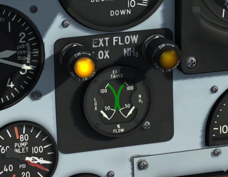
External tanks fuel flow indicator and lights.
An indication of flow of liquid oxygen and ammonia from the external tanks to their respective internal tanks is displayed in the cockpit on a dual-reading gauge [4, fig. 5-1], on the instrument panel. The gauge is powered by the primary DC bus.
Two pointers travel over separate arcs of calibration which have 0%, 50%, and 100% markings. The left calibration arc and pointer are for the left external tank (liquid oxygen), and the right calibration arc and pointer are for the right external tank (ammonia). During initial pressurization or jettison, the gauges should read approximately 50%. Both pointers should indicate 100% when the engine thrust is at 100%.
Two amber "EXT. TANKS JETT READY" indicator lights [4, fig. 5-1], on the instrument panel, are powered by the primary DC bus.
The left light is placarded "LOX TANK" and the right light is placarded "NH3 TANK." These lights, when on, indicate that the external tanks are ready to be released. The lights come on when the intervalometer times out and the liquid oxygen transfer valve closes, and go out when their respective tanks are released.
Note: The press-to-test lights in the cockpit can be tested by pressing (left-clicking with the mouse) the light housing. Left-clicking with the mouse a second time will return the light to its normal operating state.
See also:
X-15A-2 Propellant Supply System