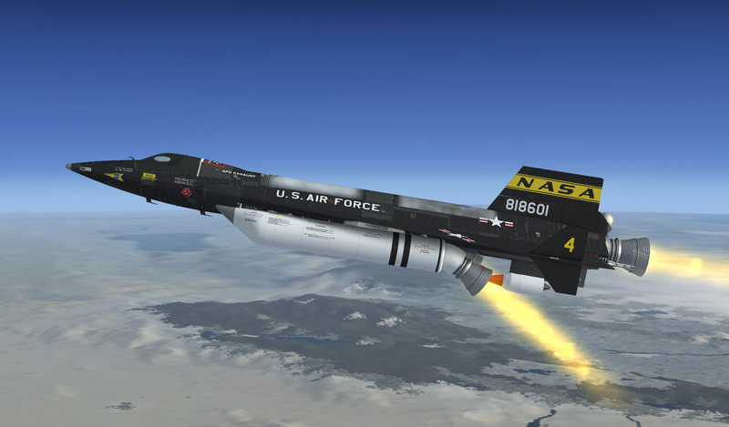
Solid fuel rocket boosters are installed on the Xtreme Prototypes X-15AD-4.
This addon includes three variations of a fictitious delta wing X-15AD-4 aircraft with rocket engine nozzle extensions and solid rocket boosters, based on different proposed configurations for future X-15 airplanes.
Note: Make sure the parking brake is applied ("CTRL+.") before starting the igniter-idle phase with this aircraft. The igniter-idle phase is in reality the jet engine starting phase that generates enough thrust to move a small aircraft like the X-15 on the runway if the parking brake is not applied. This is due to the immense power of the three engines combined.
(Did you know? The XLR-99 engine's second-stage igniter phase by itself produced 1500 pounds of thrust on the real aircraft.)
One Thiokol "Castor 1", 45,000-pound solid rocket booster [5, fig. 3-3] may be mounted on the lower left and lower right side fairings on the X-15AD-4 airplane.
On the proposed aircraft, the rocket boosters would have allowed for a significant increase in altitude, up to 520,000 feet at a maximum velocity of 8700 feet per second. They were not provided to allow for an increase in speed.
Note: Maximum speed and altitude depends on limitations in the simulator.
A fictitious solid rocket booster option switch [26, fig. 5-3], on the service panel, is provided for choosing whether or not the X-15AD-4 solid rocket boosters are installed.
Make sure this switch is set to INSTALLED if you want to fly the X-15AD-4 with the solid rocket boosters installed.
Note: Rocket boosters are emptied when the solid rocket booster option switch is moved to NOT INSTALLED, then back to INSTALLED. Boosters will need to be refueled (refer to "Express Fill Button").
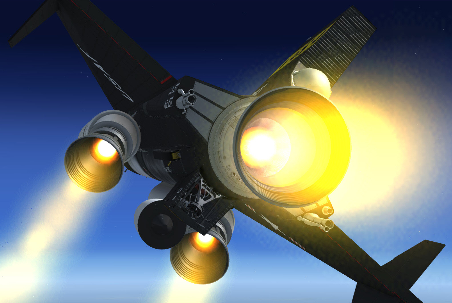
Solid rocket boosters after ignition (Prepar3D® v4 screenshot).
The solid rocket boosters are ignited as soon as the main XLR-99 engine is fired (when moving the throttle [12, fig. 5-4] inboard to START 50% at the end of the ignition sequence). They will burn for approximately 50 seconds after which they need to be released either manually or automatically.
Some modern solid fuel rocket boosters can be extinguished after they are fired. We know however that this is something the type of boosters installed on the AD-4 could not do. But we needed to provide a way to shut them off to go around the simulator's bad habit of starting the engines when positioning the aircraft in mid-air with the map or with the slew commands. This is why the boosters will shut down if the throttle is moved outboard to OFF.
To re-ignite the boosters after they were shut down, you will need to move move the igniter-idle switch [53, fig. 5-1] to OFF, then back to IGNITER. When the throttle is moved inboard to START 50%, the three engines will fire, including the rocket boosters.
Should it become necessary to release the rocket boosters in an emergency before a normal engine burnout, switches are provided on the solid rocket boosters control panel [18, fig. 4-1] on the left console to allow the pilot to manually release the boosters. The solid rocket boosters on the X-15AD-4 will shut off automatically before they are jettisoned.
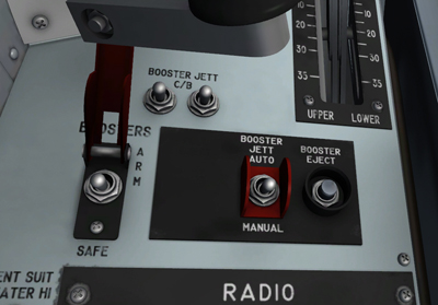
Solid rocket boosters control panel on the left console.
These two-position switches [1-2, fig. 5-6], labeled "BOOSTER JETT C/B", on the solid rocket boosters control panel [18, fig. 4-1] (on the left console), apply or remove battery bus power to the rocket booster release circuits and controls.
This two-position, guarded switch [3, fig. 5-7], on the solid rocket boosters control panel [18, fig. 4-1] (on the left console), is powered by the battery bus and controls arming of the rocket booster release circuits.
With the switch in the guarded SAFE position, the release circuits are open, and the release system is inoperative. Raising (clicking) the guard and placing the switch at ARM arms the rocket booster release system.
This two-position switch [4, fig. 5-7], on the solid rocket boosters control panel [18, fig. 4-1] (on the left console), is powered by the primary DC bus and controls selection of the automatic or manual mode of booster release.
Placing the switch at AUTO (solid rocket booster jettison safe-arm switch [3, fig. 5-7] at ARM) activates the automatic mode of the booster release system. When normal engine burnout occurs, the solid rocket boosters are automatically released.
Placing the switch at MANUAL (with the solid rocket boosters jettison safe-arm switch at ARM) activates the manual mode of the booster release system. To release the tanks, the pilot must press the solid rocket boosters jettison button (see below).
This gray button [5, fig. 5-7], on the solid rocket boosters control panel [18, fig. 4-1] (on the left console), is powered by the battery bus.
Momentarily depressing this button (with the solid rocket booster jettison safe-arm switch [3, fig. 5-7] at ARM) releases the solid rocket boosters.