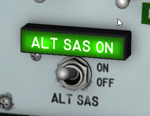
The alternate SAS indicator light and switch.
Note: The alternate stability augmentation system is not supported in this software version. Consequently, the ASAS switch and light do not perform any simulator function, other than being animated to simulate ASAS-related procedures.
The ASAS switch and indicator light are on the SAS/ASAS/RAS panel [48, fig. 5-1], on the main instrument panel.
This two-position switch [11, fig. 5-2], labeled "ALT SAS", permits automatic changeover to the ASAS at pilot option. When the switch is at OFF, the system has power applied and is in a stand-by condition. When the switch is moved to the ON position, a malfunction in the roll channel of the SAS, or placing of the SAS roll function switch [6, fig. 5-2] at STD BY, will cause the transfer relay to be energized, thereby connecting the ASAS input signals to the pitch-roll serve cylinders and disconnecting the SAS input signals. The switch is powered by the primary DC bus.
A placard-type green indicator light [10, fig. 5-2], labeled "ALT SAS ON", informs the pilot when the ASAS is engaged and operating. The light is powered by the primary DC bus and can be tested through the indicator, caution, and warning light test circuit.
See also:
Alternate Stability Augmentation System
Stability Augmentation System (SAS)