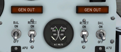
Generator switches, indicators and voltmeter.
A three-position switch [21, fig. 5-1] on the instrument panel controls operation of the No. 1 AC generator by means of battery bus power. The switch is spring-loaded from the RESET position to ON. When the switch is OFF, the generator is taken "off the line". When the generator is "off the line", because the switch is at OFF or because of a momentary generator malfunction, the switch must be moved to RESET momentarily to bring the generator "on the line" and then released to ON to maintain the generator "on the line".
Note: Neither generator will operate unless the APU for the respective generator is also operating and driving the generator.
To bring the No. 1 generator "on the line" initially, the switch must be moved from OFF to RESET momentarily and then released to ON. It is not necessary to move the switch to OFF when the No. 1 APU is shut down, because the No. 1 generator underfrequency protective relay will have tripped the generator off.
Note: If either generator is operating and "on the line", most external power is automatically disconnected. Power to the battery bus, certain heaters, ready-to-launch light, liquid oxygen level probe, and stabilization of stable platform remains on.
Switch positions and operation of this switch [26, fig. 5-1], on the instrument panel, are identical to those for the No. 1 generator control switch, except that, obviously, the No. 2 switch controls the No. 2 generator.
This guarded, two-position switch [23, fig. 5-1], on the instrument panel, controls connection of the emergency battery to the battery bus. Normally, the switch is in the guarded OFF position. Raising the guard and moving the switch to ON connects the emergency battery directly to the battery bus.
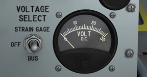
DC voltmeter and switch.
This three-position switch [13, fig. 5-3], on the center pedestal, allows strain gauge or primary DC bus voltage to be monitored. When the switch is at OFF, the DC voltmeter [12, fig. 5-3] is disconnected. Moving the switch to STRAIN GAGE connects the DC voltmeter to the strain gauge power. When the switch is at BUS, the voltmeter is connected to the primary DC bus.
Note: Strain gauges (and sensors) are not simulated in this software version. However, the DC voltmeter will indicate 24 volts when the switch is at STRAIN GAGE, indicating a normal strain gauge circuit.
See also:
Electrical Power Supply System Indicators