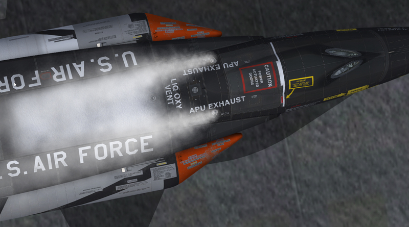
APU exhaust pipes on top of the forward fuselage of the X-15A-2 SE.
The airplane is equipped with two auxiliary power units (APUs) [8, fig. 3-1] that are set side-by-side in a compartment in the forward fuselage. Each unit is a completely automatic, constant-speed, turbine drive machine that transmits power to, and provides structural support for, an AC generator and a hydraulic pump.
Propellant for each auxiliary power unit is provided by an independent feed system, using helium pressure to move the monopropellant, hydrogen peroxide.
The two auxiliary power units with their respective feed systems are identified as system No. 1 and system No. 2. Their operation is completely independent of each other, and each furnishes one half of the power required. If one unit should fail, the other will provide sufficient electrical and hydraulic power for limited flight capabilities.
Each auxiliary power unit is started and stopped by a switch in the cockpit. When an APU is turned on, a solenoid-type shutoff valve is opened to allow hydrogen peroxide from the propellant feed system to flow into the unit.
The propellant is routed first through a gear case for cooling purposes. Nitrogen gas is also introduced into the gear case to supply a constant 8 to 10 psi pressure to prevent foaming of the gear case lubricant by vacuum at high altitude. In addition, nitrogen gas is also introduced into the upper turbine bearing area for cooling.
After leaving the gear case, the propellant moves through a flow control valve that is modulated to open or close to provide stabilization through a speed control system consisting of a tachometer generator and a frequency detector. Any turbine overspeed condition is sensed by an overspeed sensing element in the speed control system which will automatically act to close the shutoff valve. When the shutoff valve is closed, fuel flow stops and the unit shuts down. The APU shutoff valve is fitted with a drain that opens when the valve is closed, to relieve any excess pressure in the line downstream of the shutoff valve.
After passing through the flow control valve, the hydrogen peroxide enters a decomposition chamber containing a catalyst bed. This catalyst bed is made up of a series of silver and stainless-steel screens which act to decompose the hydrogen peroxide into a high-pressure gas mixture of superheated steam and oxygen.
(The decomposition chamber is heated electrically from the carrier airplane to ensure a fast start under "cold soak" conditions in case of an emergency.)
The superheated steam and oxygen mixture enters a nozzle box in the turbine housing. Here, five nozzles convert pressure energy of the fluid into kinetic energy and direct the flow of gas against a turbine wheel.
The turbine, acting through a reduction gear train, transmits power to the AC generator and hydraulic pump. The turbine wheel is housed within an exhaust casing which is designed to contain any buckets that might separate from the wheel during an overspeed operation. The exhaust casing collects spent gases that have passed through the turbine wheel and exhausts them overboard.
A gear casing assembly contains the reduction gearing, accessory drive pads, cooling passages, provisions for lubrication, and a drive for the tachometer generator.
For information on nitrogen cooling of the upper turbine bearing of each APU, refer to "APU Cooling Switch".
In this section:
APU and Ballistic Control Propellant Feed System
Hydrogen Peroxide Transfer System
See also:
Generator and APU Cooling and Pressurization
Electrical Power Supply System
Hydraulic Power Supply Systems