The two AC generators and APU upper turbine bearing areas are cooled and pressurized by gaseous nitrogen after it has been converted from a liquid state.
When the pressure-cooling lever [9, fig. 5-9] and cockpit helium switch [27, fig. 5-9] are ON, X-15 system liquid nitrogen flows to two normally open shutoff valves, one for each generator cooling shroud and each APU upper turbine bearing area. These valves are electrically connected to the APU switches [17, 30, fig. 5-1] so that when either APU switch is turned OFF while the APU cooling switch [17, fig. 5-9] is at SINGLE, its respective valve closes. This shuts off the liquid nitrogen supply to the affected units regardless of the position of the pressure-cooling lever.
After passing through the shutoff valves, the liquid nitrogen is routed to pressure restrictors, where it is changed to a gaseous state before moving on to the generators and turbines. The gaseous nitrogen, after it has absorbed heat from the generator and APU upper turbine bearing area, is exhausted into the APU compartment.
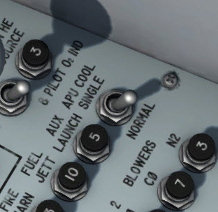
APU cooling switches.
This two-position switch [17, fig. 5-9], at the aft end of the right-hand console, is labeled "APU COOL". It is powered from the primary DC bus through the APU switches [17, 30, fig. 5-1].
With the switch at NORMAL, primary DC bus power is cut off from the shutoff valves which control liquid nitrogen flow to the APU's and AC generators, and the valves are de-energized open.
With the switch at SINGLE, each valve will be energized closed if its respective APU switch is OFF, or de-energized open if its respective APU switch is ON.
During single-APU operation, if excessive upper bearing temperatures are encountered on the operating APU, the switch should be moved to NORMAL. This will increase the volume of liquid nitrogen flow through individual flow restrictors, thus providing more efficient cooling of the bearing. If the upper bearing temperature of the non-operating APU is excessively low, the switch should be moved to SINGLE, to shut off cooling nitrogen flow to the non-operating APU.
See also:
Air Conditioning and Pressurization System Controls and Indicators