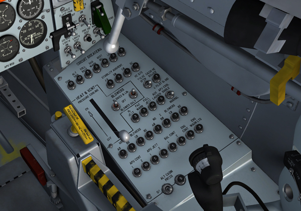
Air conditioning and pressurization system controls on the right console.
The pressure-cooling lever [9, fig. 5-9], on the right console, controls both the air conditioning and pressurization of the cockpit and the electronic equipment compartments. The lever has two positions, ON and OFF.
When the lever is moved forward to ON, the system manual shutoff valve opens, allowing liquid nitrogen to flow throughout the entire system. With the lever at OFF, the system is inoperative.
In free flight, the nitrogen gas for the pilot's pressure suit system is also controlled by the pressure-cooling lever.
This 2-position switch [27, fig. 5-9], on the right console, controls primary DC bus power to the alternate cabin pressurization system shutoff valve. The switch, labeled "ALT CABIN PRESS", turns on the alternate cabin pressurization system arming circuit when set to ON. When the switch is at OFF, the alternate cabin pressurization system arming circuit is de-energized.
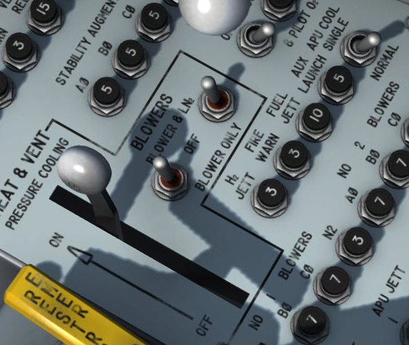
Blower switches.
There are two blower toggle switches [10, fig. 5-9] on the right console. The three-position switches, powered by the primary DC bus, are labeled "BLOWERS".
When the switches are at OFF, the blowers are off, the liquid nitrogen shutoff valves to the injectors are de-energized open, and the pressure control valves are de-energized closed.
With the switches at BLOWER & LN2, electrical power is applied to the blowers, the liquid nitrogen shutoff valves to the injectors are de-energized open, and the pressure control valves are energized open.
With the switches at BLOWER ONLY, electrical power is applied to the blowers, the liquid nitrogen shutoff valves to the injectors are energized closed, and the pressure control valves are de-energized closed.
Both the No. 1 and No. 2 blowers are powered by the No. 1 primary AC bus. The No. 1 and 2 solenoid shutoff valves are powered by the primary DC bus. The blowers are protected by circuit breakers on the circuit-breaker panel.
Helium tank pressure to the liquid nitrogen tank is controlled by a two-position toggle switch on the circuit-breaker panel [11, fig. 5-9] on the right console. The switch is labeled "CABIN SOURCE He S/O VALVE".
With the switch at CLOSED, primary DC bus power closes a solenoid-operated shutoff valve in the helium line upstream of the helium tank. With the switch at OPEN (forward), the solenoid-operated shutoff valve in the helium line is de-energized to the open position. The valve is used to isolate the air conditioning and pressurization system helium supply from the main propellant helium source as long as the former remains at or above 3000 psi. If the air conditioning and pressurization system helium supply drops below 3000 psi before launch, the valve should be opened to top off the helium supply.
This unlabeled (yellow) handle [2, fig. 4-3] is used to position a valve which controls flow of gaseous nitrogen to the inner surface of the windshield inner panels. It is on the right side of the canopy, below the windshield panel.
Flow of the nitrogen is shut off with the handle rotated down. Rotating the handle counterclockwise 90 degrees (to horizontal) opens the valve and permits flow of X-15 or augmented system gaseous nitrogen to the windshield antifogging manifold.
Note: In the virtual cockpit, windshield frost or fogging will melt in about 10 seconds after moving the windshield heater switches [36, fig. 5-1] to ON or turning the windshield antifogging handle to horizontal. The switches and the handle will respond to a single mouse click.
This unlabeled (gray) handle [3, fig. 4-3] is used to position a valve which controls purging flow of gaseous nitrogen between the windshield panels. The handle is on the right side of the canopy, below the windshield panel.
Flow of the purging gas is shut off with the handle rotated down. Counterclockwise rotation of the handle 90 degrees (to horizontal) opens the valve and permits purging gas flow.
A ram-air lever [16, fig. 5-3], on the left side of the center pedestal, controls the operation of the ram-air system. It is labeled "RAM AIR" and has OPEN and CLOSED positions. The lever is mechanically linked to the ram-air scoop [21, fig. 3-1] and the ram-air shutoff valve, and electrically connected to the cockpit safety (dump) valve. The ram-air scoop is on the lower center line of the fuselage, just aft of the nose wheel well.
When the lever is moved (dragged with the mouse) to OPEN, the ram-air shutoff valve and the ram-air scoop are opened to allow ram air to enter the system. At the same time, the cockpit safety valve is opened, allowing the cockpit and electronic equipment compartment pressure to be depleted and the ram air to be circulated through these areas.
When the lever is at CLOSED, the ram-air shutoff valve and the ram-air scoop close. The cockpit safety valve is closed when the ram-air lever is at CLOSED.
Ram air to the cockpit is controlled by the cockpit ram-air knob [11, fig. 5-3], on the center pedestal. The knob is mechanically linked to a shutoff valve that is ducted off the main ram-air line. When the knob is pulled (dragged with the mouse) straight out, the two-way shutoff valve opens to allow ram air (if the ram-air lever [16, fig. 5-3] is at OPEN) to enter the cockpit. Pushing the knob in closes off the ram air to the cockpit.
The cockpit ram-air knob should be pushed in when the X-15 liquid nitrogen system is in use (blower switches [10, fig. 5-9] at BLOWER & LN2); otherwise, recirculating cooling gas will be bled from the ducting system.
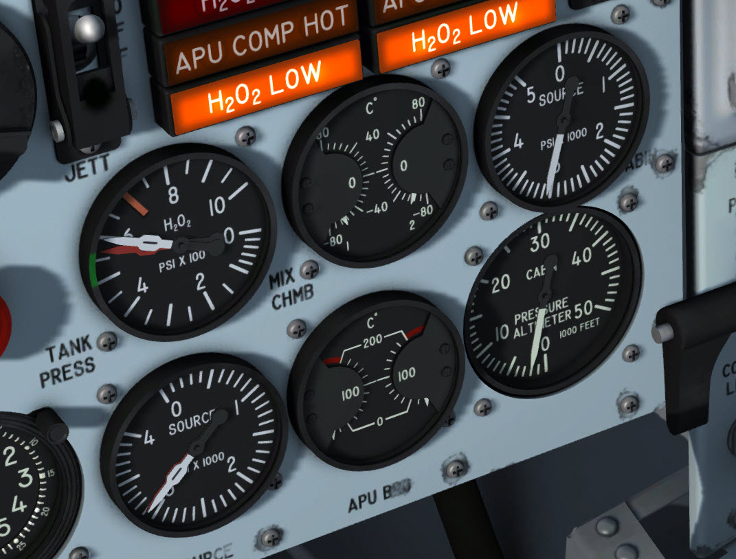
Air conditioning and pressurization instruments on the main panel.
A cabin helium source pressure gauge [40, fig. 5-1], on the lower right of the instrument panel, indicates the helium pressure available to operate the air conditioning and pressurization system. The gauge is calibrated from 0 to 5000 psi. The gauge and pressure transmitters are powered by the 26-volt AC bus and protected by a circuit breaker [12, fig. 5-9] on the circuit-breaker panel on the right console.
The dual-pointer mixing chamber temperature gauge [42, fig. 5-1] shows the temperature in the No. 1 and No. 2 mixing chambers. Power is supplied by the No. 1 primary AC bus to amplifiers within the gauge unit, activating the indicator needles. The gage shows temperature in degrees centigrade and is calibrated in 10° C increments from -80° C to +80 ° C.
The pressure altitude of the cockpit is shown by a cabin pressure altimeter [41, fig. 5-1] on the lower right corner of the instrument panel. The indicator is vented only to pressure within the cockpit, and operates on the aneroid principle.
See also:
Cockpit Air Conditioning and Pressurization
Operation of Air Conditioning and Pressurization System
Generator and APU Cooling and Pressurization