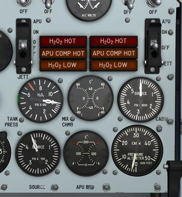
APU switches, indicators and gauges.
There are two APU switches [17 and 30, fig. 5-1] on the instrument panel, one for control of each auxiliary power unit and its associated feed system.
When either switch is turned to ON, battery-bus power is used to open the helium shutoff valve in the related propellant feed system, allowing helium pressure to move the hydrogen peroxide through the feed lines. At the same time, power is applied to the opening circuit of the related APU shutoff valve. This permits the propellant to flow to the auxiliary power unit.
Turning the switch to OFF closes the helium shutoff valve (if the ballistic control switch [18 and 27, fig. 5-1] is at OFF), shutting off the helium supply. If the ballistic control switch is at ON, the OFF position of the APU switch will not close the helium shutoff valve. At the same time, the APU shutoff valve closes, shutting off the flow of the propellant to the unit.
The JETT position, powered by the primary DC bus, is used if an emergency arises and it is desired to jettison the propellant overboard. The switch is guarded to prevent it from being accidentally moved to the JETT position.
When the switch is turned to JETT, the following occurs: The helium shutoff valve in the feed system opens, or remains open if it is already so, allowing the helium to continue to force the hydrogen peroxide through the feed lines. Concurrently, the APU shutoff valve closes and a jettison and ballistic control valve in the feed system opens to the jettison position. The jettison and ballistic control valve serves both as a shutoff valve for propellant supply to the ballistic control system and as a propellant jettison control. As this valve opens to the jettison port, the propellant is routed through a line that dumps overboard [6, fig. 3-2] at the aft end of the airplane.
Two APU compartment amber overheat caution lights [29, fig. 5-1] are adjacent to their related APU switches [17 and 30, fig. 5-1] on the instrument panel. The lights are powered by the battery bus.
A thermoswitch in each APU accessory drive compartment is set to energize the light when the temperature in the compartment rises to approximately 525° F. The lights read "APU COMP HOT" when on. If either light comes on, the related auxiliary power unit should be shut down immediately.
See also:
Generator and APU Cooling and Pressurization