Pitot-static system instruments on left side of the main panel.
The white T-type landing gear handle [80, figure 5-1] is on the main instrument panel, to the left of the airspeed/Mach indicator.
The handle is mechanically linked to the retractable pitot tube assembly [38, fig. 3-1]. When the handle is pulled straight aft approximately 8 inches, the retractable pitot tube door opens and the pitot tube extends. When the handle is pushed back to its forward position, the pitot tube retracts and the door closes.
This two-position switch [6, fig. 5-3] is on the center pedestal and is labeled "BALL NOSE." With the switch at ON, electrical power is available for excitation of the bail nose servos.
This push-button type switch [7, fig. 5-3] on the center pedestal is labeled "BALL NOSE TEST" and is used to test operation of the ball nose in flight.
Depressing and holding the button applies an error signal to the ball nose transducers. This error signal electrically simulates a predetermined airplane sideslip angle and angle of attack, which are presented on the angle-of-attack indicator [7, fig. 5-1] and vertical and horizontal pointers on the attitude indicator [9, fig. 5-1]. When the button is released, the ball nose should drive rapidly to an extreme position, resulting in full-scale deflection of the angle-of-attack indicator pointer and vertical and horizontal pointers on the attitude indicator. This indication should be maintained for about 2 to 3 seconds; then the ball nose should drive rapidly without overshoot to indicate the actual airplane sideslip angle and angle of attack.
Note: Full-scale deflection of the angle-of-attack indicator pointer and vertical and horizontal pointers on the attitude indicator when the button is released and the subsequent return to normal readings, are positive indications of proper operation of the ball nose.
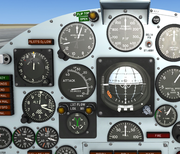
A three-pointer accelerometer [8, fig. 5-1], on the instrument panel, shows positive and negative G-loads.
One pointer continuously indicates acceleration forces. Two recording pointers indicate maximum positive and negative G encountered. The recording pointers may be reset by clockwise movement (single mouse click) of the reset knob on the lower left corner of the instrument.
This single-pointer gauge [10, fig. 5-1], on the instrument panel, shows the dynamic pressure in front of the aircraft.
Clicking the instrument front glass with the mouse will show/hide the optional radio-magnetic indicator that occupies the same space on the center panel.
The altimeter [3, fig. 5-1], on the instrument panel, has standard 1000 and 100-foot pointers and a 10,000-foot pointer extending from a movable center disk to the edge of the dial, so that it cannot be obscured by the other pointers. The center disk also has a wedge-shaped cutout through which a set of warning strips appear at altitudes below 16,000 feet. This altimeter offers improved readability and gives warning when an altitude of less than 16,000 feet is entered.
The airspeed/Mach indicator [3, fig. 5-1], on the instrument panel, has an airspeed needle fixed to a rotating plate with a range of 80 to 850 knots. The needle also indicates Mach number when airspeed is above 250 knots.
The Mach scale rotates under the airspeed pointer plate and is visible through a cutout in the plate at airspeeds above 250 knots. The Mach scale rotates with altitude changes so that the indicating pointer will show the Mach number that equals the indicated airspeed for the particular flight altitude.
The indicator has an adjustable airspeed setting index marker that is moved to the desired position by a knurled knob at the lower right corner of the instrument ring. The index marker can be used for referencing any desired in-flight speed as well as landing speed.
A movable red hand is set by maintenance personnel to indicate 700 knots EAS. As altitude is increased, changes in outside air density cause the hand to move to a higher IAS reading.
A remote-type angle-of-attack indicator [7, fig. 5-1], on the instrument panel, is electrically driven by power from both the No. 2 primary AC and primary DC busses. The ball nose measures the angle between the relative wind and the fuselage reference line. The attack angle so determined is then transmitted to the indicator. The indicator has a range from 10 degrees nose down to 40 degrees nose up.
A rate-of-roll indicator [49, fig. 5-1], on the instrument panel, is electrically powered by the primary DC bus. The rate-of-roll inclicator indicates the roll rate in degrees per second for right and left roll from 0 to 200 degrees per second.
See also:
Stable Platform Controls and Indicators