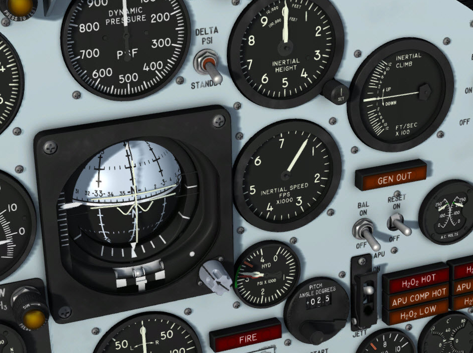
Stable platform instruments on upper right section of the main panel.
Note: In referring to electrical power sources in the following paragraphs, it is considered that the stable platform switch [33, fig. 5-1] is positioned at INT and that the system controls and indicators are being powered from the X-15 airplane.
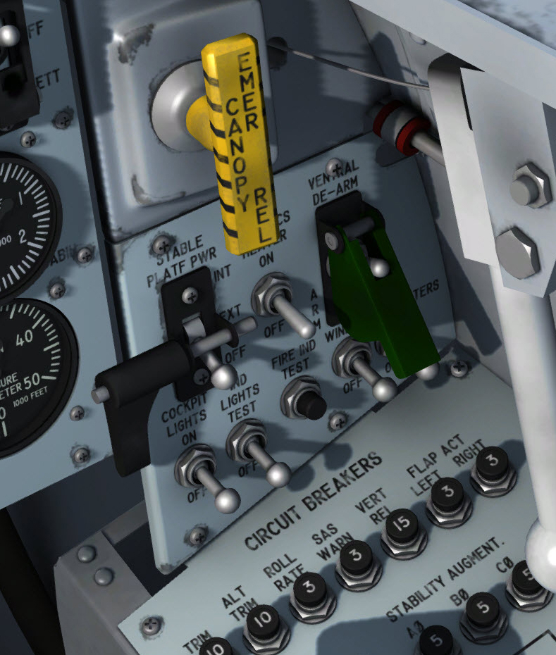
The guarded stable platform power switch is on the right side panel.
The guarded stable platform power switch [33, fig. 5-1] provides a means for selecting stable platform power, either from the carrier airplane or from the X-15. The switch is on the instrument panel right wing and is labeled "STABLE PLATF PWR". It has three maintained positions: INT, EXT, and OFF.
The OFF position is a détente position. To move the switch from OFF, the switch must be pulled out of the détente. Moving the switch to INT energizes the platform with No. 2 primary AC bus power from the APU's of the X-15.
Note: Do not turn the stable platform switch to INT when the APU's are off.
When the switch is moved to EXT, the system is energized by power units in the carrier airplane (external power switch [22, fig. 5-3] at ON).
Note: The switch should be moved from EXT to INT just before launch. However, if this is not done, power will be automatically transferred from the carrier airplane to the X-15 at time of launch.
Turning the switch to OFF shuts off all power to the platform system.
The guard must be removed with a single mouse click before the switch can be actuated. The guard cannot be reinstalled once removed unless the flight is reset.
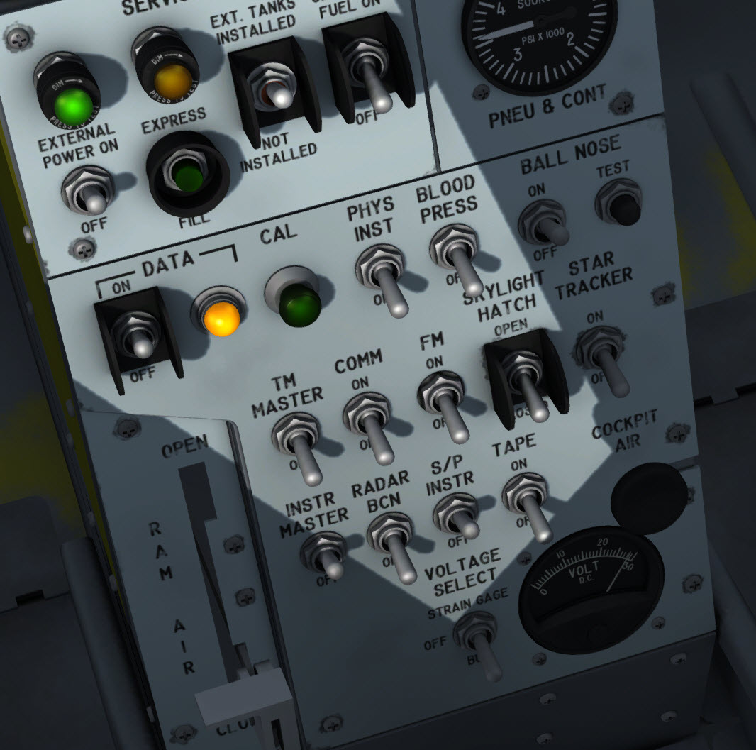
The stable platform instrument switch is on the center pedestal.
This two-position switch [10, fig. 5-3] on the center pedestal is labeled "S/P INSTR". The switch controls power to the stable platform indicators in the cockpit. It is used during ground checks of the stable platform system to interrupt power to the instruments when their operation is not required to perform the check-out. With the switch at OFF, power to the stable platform instruments is interrupted. Except during ground checks, the switch must be at ON.
This two-position switch [12, fig. 5-1] is on the main instrument panel and has "DELTA PSI" and "STANDBY" positions. With the switch at STANDBY, side-slip signals derived from the ball nose are presented on the attitude indicator's vertical pointer [9, fig. 5-1]. With the switch at DELTA PSI, side-slip (or delta track) signals derived from the stable platform are presented on the vertical pointer of the attitude indicator.
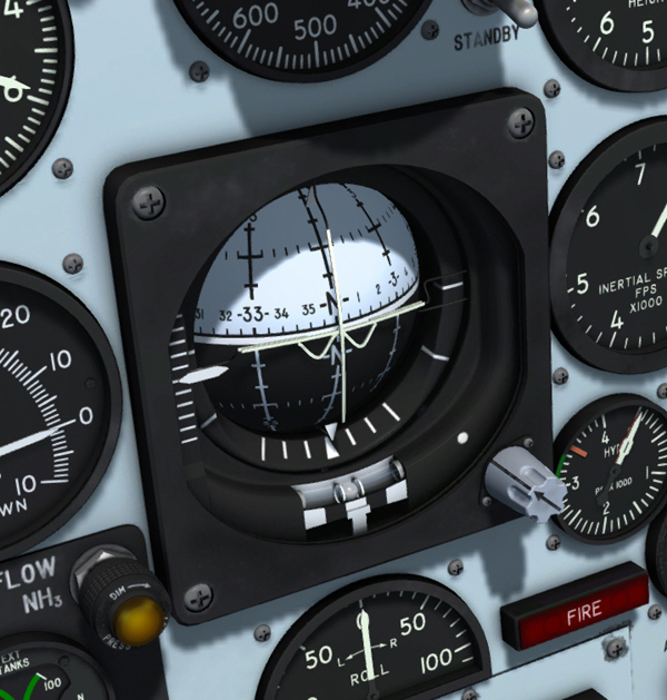
Attitude indicator.
The attitude indicator [9, fig. 5-1], on the instrument panel, is powered by the primary DC bus and the No. 2 primary AC bus.
It is a pictorial-type instrument that combines displays of attitude and azimuth on a universally mounted sphere displayed as the background for a miniature reference airplane.
The sphere (remotely controlled by the stable platform) is free to rotate 360 degrees in pitch, roll, and azimuth. The miniature reference airplane is always in proper physical relationship to the simulated earth, horizon, and sky areas of the background sphere.
The horizon on the sphere is represented as a solid white line. On this horizon line is an azimuth scale graduated in 5-degree markings from 0 through 360 degrees. Above the horizon line, the sky is indicated by a light-gray area. Below the horizon line, the earth is indicated by a dull-black area. The sphere is marked by meridian lines spaced every 30 degrees. Fitch angle is referenced to the center dot of the fixed miniature airplane by horizontal marks spaced every 10 degrees on the meridians.
A pitch-adjustment knob on the lower right side of the instrument electrically rotates the sphere to the proper position in relation to the miniature airplane to correct for pitch attitude changes. Clockwise rotation of the knob causes the horizon line to deflect upward from the airplane index. Rotating the knob counterclockwise causes the horizon line to deflect downward. Trim setting is automatically and gradually canceled as airplane attitude approaches the vertical in climb or dive to ensure a true vertical indication. It returns automatically when level flight is resumed.
Note: You can use the radio-magnetic indicator's synchronizer knob to calibrate the sphere's heading indicator. See "Radio-Magnetic Indicator" below.
Bank angles are read from a semicircular bank scale on the lower quarter of the instrument.
Two long pointers project across the sphere. Movement of these pointers shows airplane displacement with respect to the air in which it is flying (small angles of attack and sideslip). The horizontal long pointer is a vernier indication of the angle-of-attack slip indicator [7, fig. 5-1] on the instrument panel. This horizontal pointer moves upward when the angle of attack is increased and downward when the angle of attack is decreased. The vertical long pointer moves to the right to indicate a left sideslip, and to the left to indicate a right sideslip. The range of either pointer movement is adjustable (on the ground) to operate within ±5 to ±10 degrees.
A short horizontal pointer is on the left side of the instrument. This pitch pointer is a vernier indication for the pitch axis of the sphere and moves in the same direction as the sphere. The pointer indicates displacement in a range of ±5 degrees of that angle selected on a pitch angle set control [16, fig. 5-1].
Immediately after launch, the pilot rotates the airplane to the pitch angle that is preset on the pitch angle set control. Initially, the sphere is used to approximate this angle. As the airplane approaches to within 5 degrees of the preselected pitch angle, the small pitch pointer moves toward the center index (0). The pilot then switches his attention from the sphere to the pointer for fine adjustments. The pointer will remain at the zero position as long as the preset pitch angle is maintained.
A turn-and-slip indicator is on the lower portion of the instrument below the bank angle scale. The rate-of-turn needle is powered by the 26-volt AC bus and the No. 2 primary AC bus. Immediately after electrical power is applied, an "OFF" flag on the lower left section of the indicator retracts. Failure of either AC or DC power causes the "OFF" flag to reappear.
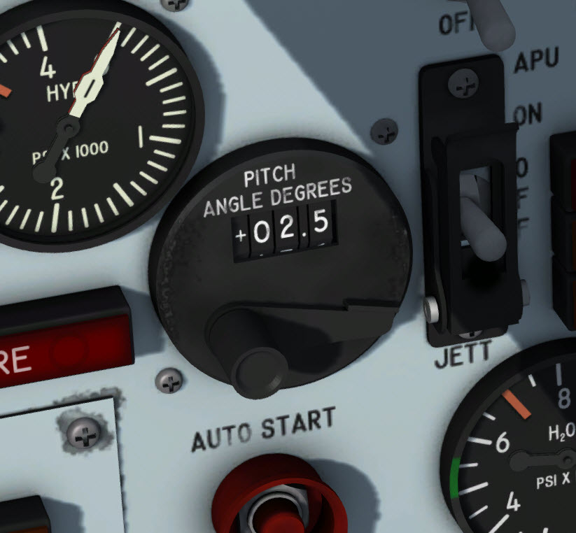
The pitch-angle set control.
A pitch-angle set control [16, fig. 5-1], powered by the primary DC bus and the No. 1 primary AC bus, is on the instrument panel, next to the attitude indicator. The control is used in conjunction with the small pitch pointer on the attitude indicator [9, fig. 5-1]. The angle that is set on this control is the pitch angle the pilot will attain for either the climb or the re-entry phase of a mission.
The instrument consists of four counters and a pitch angle set controller knob and lever. Rotating the knob clockwise sets up the desired pitch angle on three of the counters. The number on the far right counter is preceded by a dot to indicate the reading is in tenths of a degree. Counter range is from 0 to 90 to permit selection of any pitch angle up to 90 degrees. Rotating the knob counterclockwise (right clicking with the mouse) returns the three counters to 0. The lever, adjacent to the knob, can be rotated upward or downward (left clicking with the mouse) to change the sign (negative or positive) of the selected pitch angle. When the lever is moved upward, a minus (-) sign shows on the left counter; downward movement produces a plus (+) sign.
For additional information, refer to "The X-15 Experience".
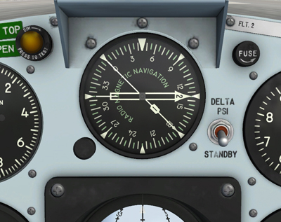
Optional RMI.
An optional radio-magnetic indicator is provided on the center panel. To show/hide the RMI, click the glass in front of the dynamic pressure gauge [10, fig. 5-1], above the attitude indicator [9, fig. 5-1].
The radio-magnetic indicator incorporates one movable compass card, two direction pointers, and one fixed index card.
Note: The index card can be rotated in the simulator by left or right-clicking the synchronizer knob. The card was fixed in the original X-15.
The compass card displays azimuth reference with respect to the surface of the earth. The compass card is synchronized with the stable platform of the flight data system. A push-to-set synchronizer knob at the lower left side of the indicator permits adjustment of the compass card to read airplane azimuth displacement either from magnetic north or from the high range centerline. The knob may be turned (with the mouse wheel) to accurately synchronize the card with the stable platform during initial operation of the system.
Note: Turning the synchronizer knob will also affect the the sphere in the attitude indicator [9, fig. 5-1].
Magnetic heading information.
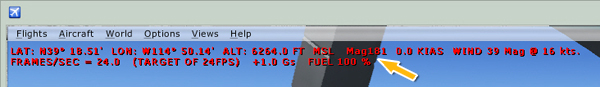
Note: You can use the magnetic heading information displayed in the top left section of the simulator's main window to synchronize the compass card in the RMI and the sphere in the attitude indicator [9, fig. 5-1] (see "Attitude Indicator" above). Press "SHIFT-Z" to show/hide the heading information.
The double-barred pointer is synchronized with the antenna of the automatic radio direction finder (ADF) system. It reads displacement between the airplane centerline and a course to the ADF ground station.
The single-barred pointer is synchronized with the VOR antenna. It reads displacement between the airplane centerline and a course to the VOR ground station.
The radio-magnetic indicator is powered by the primary DC bus and the No. 1 primary AC bus.
For more information, refer to "Radio Communication and ADF/VOR System".
The inertial height indicator [15, fig. 5-1], powered by the primary DC bus and the No. 1 primary AC bus, is on the instrument panel. The indicator is coupled to the stable platform system computer to automatically indicate any change in height. The computer, in turn, determines the height from vertical accelerations measured by a vertical accelerometer in the stable platform. Height is measured from an arbitrary reference line. This reference line may be determined in one of several ways - pressure altitude, ground control radar, etc. The inertial height indicator has a long 10,000-foot pointer and a short 100,000-foot pointer. Before launch, the pilot should readjust the height indicator (by turning a knob labeled "SET" on the face of the instrument) to his height in relation to the arbitrary reference line to eliminate possible cumulative errors.
The speed (velocity) indicator [14, fig. 5-1] is a single-pointer instrument coupled to the stable platform system computer to indicate airplane trajectory velocity. The computer determines this trajectory velocity from accelerations measured by accelerometers in the stable platform. The indicator, powered by the primary DC bus and the No. 1 primary AC bus, is on the instrument panel and reads in thousands of feet per second from 0 to 7.
This single-pointer indicator [19, fig. 5-1], on the instrument panel, displays inertial ascent and descent in hundreds of feet per second from 0 to 12. The vertical velocity indicator, powered by the primary DC bus and the No. 1 primary AC bus, is coupled to the stable platform system computer. The computer determines this vertical velocity from accelerations measured by the vertical velocity accelerometer in the stable platform.
See also:
Inertial All-Attitude Flight Data System (Stable Platform)
Pitot-Static System Instruments and Controls
Radio Communication and ADF/VOR System