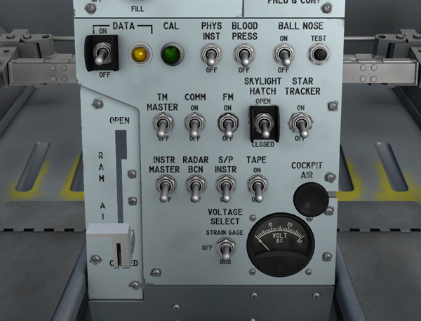
X-15 instrumentation controls and indicators on the center pedestal.
The instrumentation system records a wide variety of data on the basic airframe and airplane systems. The system is powered from the No. 2 primary AC bus and the primary DC bus. Controls and indicators for the system are on the center pedestal.
Turning this two-position switch [15, fig. 5-3] to ON energizes all instrumentation heater circuits, energizes air-borne recording instrumentation DC power circuits, and arms the gyro cage switch, strain gauge power switch, and data switch. Moving the switch to OFF electrically de-energizes all instrumentation equipment.
This two-position switch [1, fig. 5-3] energizes all airborne recording media and arms the camera and calibrate switches when it is turned from OFF to ON. The switch also turns on a neon data light next to the switch. The data light [2, fig. 5-3] blinks in synchronization with the camera timer thus providing a positive indication of correct timer operation and energizing of recorder film magazines.
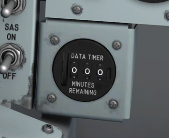
Data timer (next to the main panel left wing).
The data timer [79, fig. 5-1], located under the main panel (next to the panel left wing), shows the remaining recording time (in minutes) on the data tape recorder. Before flight, the timer is set to the maximum recording time by rotating the wheel on the left side of the instrument. A reset button is provided on the right side of the display. With the instrumentation panel energized, the data timer starts counting when both the instrumentation master power switch [15, fig. 5-3] and the tape recorder power switch [9, fig. 5-3] are set to ON.
This is a spring-loaded, push-button type switch [3, fig. 5-3] with an integral signal light. Momentarily depressing the button triggers the automatic in-flight calibration circuits used with the strain gauge transducers to record the airborne oscillographs. The signal light in the button comes on green when the button is depressed, to indicate that automatic calibration is in progress. The light continues to glow after the button is released, remaining on until the calibration is completed.
This two-position switch [9, fig. 5-3], when it is turned from OFF to ON, energizes the data tape recorder.
This two-position switch [18, fig. 5-3], when turned from OFF to ON, energizes all power circuits in the telemeter system.
Moving this two-position switch [17, fig. 5-3] from OFF to COMM energizes the telemeter commutator motor.
This two-position switch [8, fig. 5-3], when turned from OFF to ON, energizes the (FM) modulator of the telemeter system.
A physiological instrumentation switch [4, fig. 5-3] is on the instrumentation control panel. The switch, labeled "PHYS INST", allows the physiological instrumentation system to be turned on (switch moved up) or off. The switch controls primary DC bus power to the physiological instrumentation system.
This two-position switch [5, fig. 5-3], when turned from OFF to ON, energizes the pilot's blood pressure sensors that is part of the physiological instrumentation.
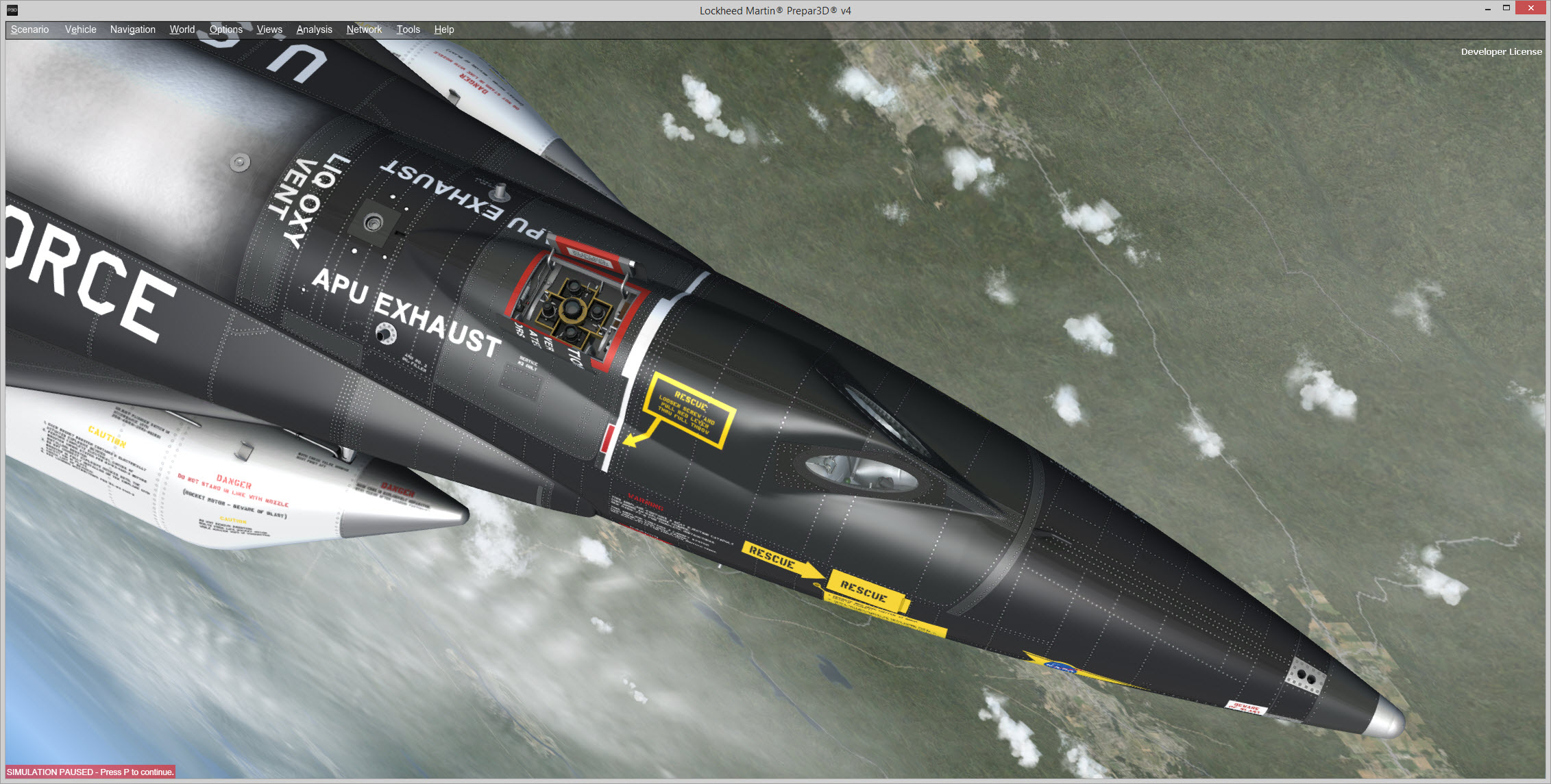
Open skylight hatch on top of the X-15AD-4, showing the scientific instruments inside their compartment (Prepar3D® v4 screenshot).
The X-15A-2 has a skylight hatch [16, fig. 3-2] on top of the instrument compartment that gives the instrumentation equipment access to the outside environment. Moving this two-position switch [19, fig. 5-3], on the center pedestal, to OPEN opens the skylight hatch on top of the instrument compartment. Moving the switch to CLOSED closes the hatch. The switch is powered by the primary DC bus.
Note: The skylight hatch is hydraulically activated. It needs hydraulic power to open or close.
When on, this amber press-to-test light [73, fig. 5-1], on the main panel, indicates that the skylight hatch [16, fig. 3-2] on top of the instrument compartment is open. If the light is off, the skylight hatch is closed. The light is powered by the primary DC bus and can be tested by pressing (left-clicking with the mouse) the lamp housing.
Note: The press-to-test lights in the cockpit can be tested by pressing (left-clicking with the mouse) the light housing. Left-clicking with the mouse a second time will return the light to its normal operating state.
The instrument compartment on the X-15A-2 addon carries an ultraviolet "star tracker" [17, fig. 3-2] and an ultraviolet horizon scanner that allow for stellar photography experiments. The star tracker, in the instrument compartment, is powered by the primary DC bus and the No. 2 primary AC bus. Moving this two-position switch [20, fig. 5-3], on the center pedestal, to ON energizes the star tracker circuits. Moving the switch to OFF electrically de-energizes the star tracker. The switch is powered by the primary DC bus.
See also: