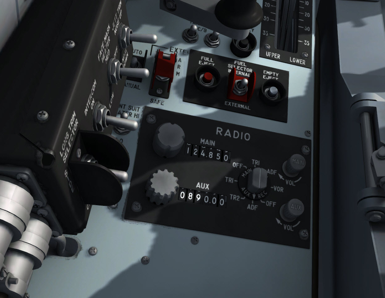
Radio control panel, on the left console.
Controls for operation of the VHF communication and ADF/VOR systems are on the radio control panel, on the left console.
Note: This section differs from the original X-15 manual to conform to the operation of the radio-communication and navigation equipment available in the simulator.
A rotary-knob type selector switch [1, fig. 5-8], on the radio control panel, controls the mode of operation, on the main or auxiliary system (channel), and also selects the antenna of best reception.
The switch is marked "MAIN REC" and "AUX REC" and has a two-headed arrow across the full diameter of the rotary knob.
On the outer perimeter of the knob is the position marking denoting the function of the system. OFF, TR1 (COM1), ADF and VOR (NAV1) are the positions for the main transceiver; TR1 (COM1), TR2 (COM2), ADF and OFF are the positions for the auxiliary transceiver.
The switch is designed so that when the arrow indicates OFF on the main system, the opposite arrow is indicating OFF on the auxiliary system.
With the switch in the TR1 (COM1) position on the VHF transceiver, the auxiliary receiver is at the ADF position. This is the normal mode of operation, and the main transceiver is connected to the VHF antenna for communication. At the same time, the auxiliary receiver is connected to the ADF antenna for automatic direction finding.
When the main receiver is at ADF position, the auxiliary transceiver is at TR2 (COM2). In this alternate mode of operation, the main receiver is connected to the ADF antenna for automatic direction finding, and the auxiliary transceiver operates from the VHF antenna for voice transmission.
When the main receiver is at VOR (NAV1) position, the auxiliary transceiver is at TR1 (COM1). In this mode of operation, the main receiver is connected to the VOR antenna for omni-directional radio range navigation, and the auxiliary transceiver operates from the VHF antenna for voice transmission.
When the function of the two transceivers is changed, the channel selectors [2-3, fig. 5-8] must be changed to provide the correct operating frequency for the individual radios.
There are two volume control knobs [6-7, fig. 5-8] on the radio control panel, marked "MAIN'' and "AUX". When either of these rotary volume controls is rotated in the direction indicated by the arrow (clockwise), the volume of the respective equipment to the pilot's headset is increased. Counterclockwise turning of either volume will diminish the volume of the equipment being adjusted.
Note: The volume control knobs in the virtual cockpit simply turn their respective radio channel audio on or off. Turn either volume control knob clockwise to turn the audio on. Turn either volume control knob counterclockwise to turn the audio off. The volume control knobs can be actuated with a single mouse click.
There are two rotary channel selector knobs [2-3, fig. 5-8] on the radio control panel used in selecting the desired channel frequency of the equipment in use. The main transceiver channel selector control provides selection of channels within the frequency range of the main VHF transmitter-receiver. A similar channel control selector enables the pilot to select channels on the auxiliary transceiver.
Note: The radio frequency units can be changed by left or right clicking the channel selector knob. The radio frequency decimals can be changed by turning the mouse wheel up or down while pointing the channel selector knob. Continuous rotation is possible by left or right clicking with the mouse and leaving the mouse button depressed until the knob is set to the desired position.
There is a channel indicator window [4-5, fig. 5-8] to the right of each channel selector knob. The upper window, marked "MAIN", shows the channel (frequency) that has been selected for the main VHF transceiver. A similar window, marked "AUX", to the right of the auxiliary receiver channel selector knob, displays the channel selected for the auxiliary receiver.
The microphone buttons (push-to-talk red switches) are located on the black handles of the center stick [8, fig. 4-1] and of the right console stick [27, figure 4-1]. Clicking either microphone button in the virtual cockpit will open the ATC window in the simulator.
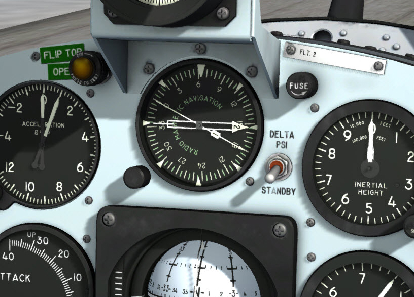
Optional RMI.
An optional radio-magnetic indicator is provided on the center panel. To show/hide the RMI, click the glass in front of the dynamic pressure gauge [10, fig. 5-1], above the attitude indicator [9, fig. 5-1].
The radio-magnetic indicator incorporates one movable compass card, two direction pointers, and one fixed index card.
Note: The index card can be rotated in the simulator by left or right-clicking the synchronizer knob. The card was fixed in the original X-15.
The compass card displays azimuth reference with respect to the surface of the earth. The compass card is synchronized with the stable platform of the flight data system. A push-to-set synchronizer knob at the lower left side of the indicator permits adjustment of the compass card to read airplane azimuth displacement either from magnetic north or from the high range centerline. The knob may be turned (with the mouse wheel) to accurately synchronize the card with the stable platform during initial operation of the system.
Note: Turning the synchronizer knob will also affect the the sphere in the attitude indicator [9, fig. 5-1].
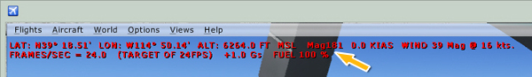
Magnetic heading information.
Note: You can use the magnetic heading information displayed in the top left section of the simulator's main window to synchronize the compass card in the RMI and the sphere in the attitude indicator [9, fig. 5-1]. Press "SHIFT-Z" to show/hide the heading information.
The double-barred pointer is synchronized with the antenna of the automatic radio direction finder (ADF) system. It reads displacement between the airplane centerline and a course to the ADF ground station.
The single-barred pointer is synchronized with the VOR antenna. It reads displacement between the airplane centerline and a course to the VOR ground station.
The radio-magnetic indicator is powered by the primary DC bus and the No. 1 primary AC bus.
Make sure the avionics is turned on before using the radio-magnetic indicator (see "Radio Function Selector Switch (Avionics Power Switch)" above).
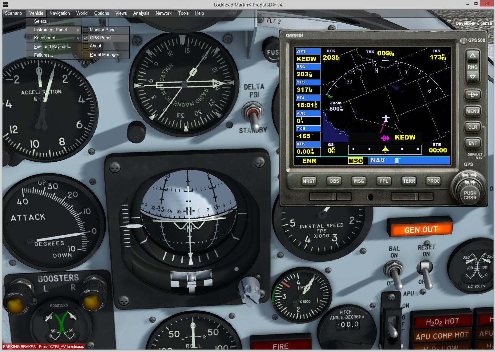
Optional GPS navigation (stock Garmin® 500 GPS included with your simulation platform).
The stock Garmin® 500 GPS receiver that comes with your simulation platform is available from the simulator's top menu bar. Refer to your simulation platform's manual for instructions on how to use the GPS. Make sure the avionics is turned on before using the GPS (see "Radio Function Selector Switch (Avionics Power Switch)" above).
Normal Operation. The normal operating procedure is as follows:
Alternate Operation. To use the auxiliary transceiver, proceed as follows: