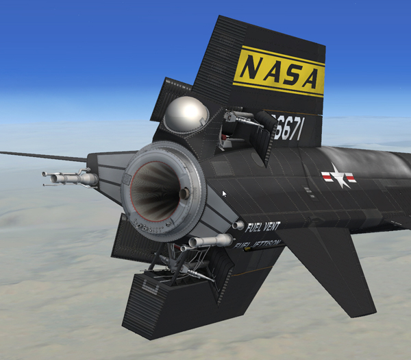
Fully opened speed brakes at the aft end of the fuselage, during descent.
The airplane has two split-flap speed brakes [3 and 34, fig. 3-1], one on the fixed portion of the upper vertical stabilizer and the other on the fixed lower vertical stabilizer.
Each speed brake consists of two symmetrical panels, hinged at the forward end. Each speed brake is operated by a dual, tandem hydraulic actuator. One segment of an actuator is powered from hydraulic system No. 1; the other segment, by hydraulic system No. 2.
Failure of one hydraulic system still permits operation of the speed brakes, however, at reduced rate under any particular air load.

Lower speed brake assembly.
The actuator valves are controlled from the cockpit by a system of cables and mechanical linkage. Follow-up mechanisms permit positioning each speed brake to any position between fully closed and fully open.
Note: Each speed brake actuator incorporates a relief valve which prevents the speed brake from extending or allows the speed brake to retract under excessive air loads, to prevent structural damage.
The speed brake handles [13 and 14, fig. 5-4] are on the left console.
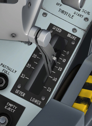
Speed brake handle on the left console.
The inboard handle controls the lower speed brake; the outboard handle controls the upper speed brake. The handles normally are locked together by an interconnecting bolt at the forward cable sectors to ensure symmetrical operation of the speed brakes. A spring-loaded lock lever on the inboard handle is designed to unlock the handles for independent speed brake operation and lock them for symmetrical operation if the interconnecting bolt is not installed.
Note: The upper and lower speed brake handles, in the virtual cockpit of the X-15A-2 SE addon, are locked together and can be dragged to the desired position with the mouse.
Speed brake position is indicated by a scale for each handle on the speed brake handle quadrant. The scales are calibrated in increments of 5 degrees. When the handles are moved to a given setting, the speed brakes will open to the position selected.
See also:
Hydraulic Power Supply Systems and Indicator