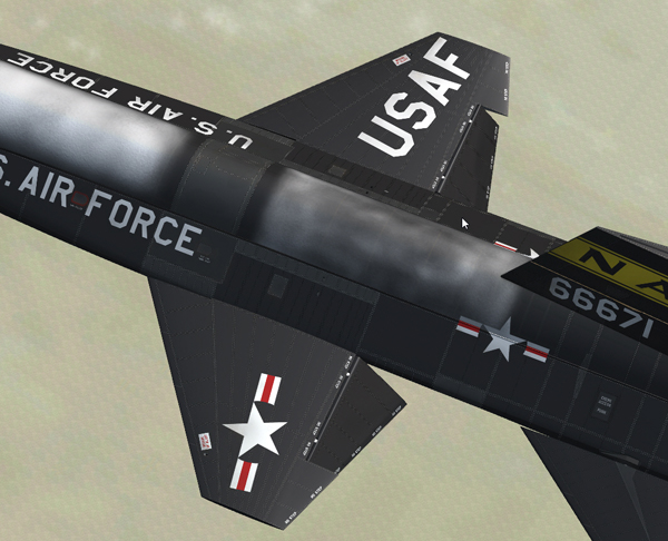
Wing flaps.
The 25½ degree swept back wing [2, fig. 3-1] has hydraulically operated flaps [12, fig. 3-2] on the inboard trailing edge of each wing panel. Flap position is controlled by an electromechanical actuator, containing two electric motors that are coupled together by a set of differential gears. The output of this actuator drives a push-pull cable system which opens the valves in the dual, tandem hydraulic flap actuators and hydraulically positions the flaps to either full up or full down.
Flap extension is possible even if one motor fails; however, the extension time is approximately twice the normal time. Normal extension from full up to full down position requires about 8 to 10 seconds.
No provisions have been made for automatic pitch correction with flap extension, nor for intermediate positioning of the flaps. However, because of the incorporation of hydraulic relief valves to limit the maximum air load on the surfaces, the flaps may partially close at speeds above 250 knots. No flap position indicator is provided.
A two-position switch [9, fig. 5-4] is on the left white control box [15, fig. 4-1], above the ballistic control stick [8, fig. 5-4]. The switch, labeled "FLAP", controls flap operation, and is powered by the primary DC bus.
It has two positions, UP and DOWN. No intermediate positioning is provided.
Note: There are no flaps on the fictitious delta wing X-15AD-4.
See also:
Hydraulic Power Supply Systems and Indicator
Electrical Power Supply Systems