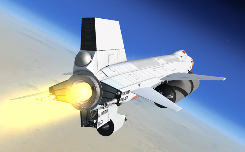
Climbing at full thrust.
The following conditions accompany normal XLR-99 rocket engine operation:
- Propellant source pressure gauge [69, fig. 5-1] – (both internal and external tanks) 3200-3800 psi, gradually decreasing.
- H2O2 source and purge pressure gauge [57, fig. 5-1] – (both internal and external tanks) 3000 psi, gradually decreasing.
- Propellant tank pressure gauge [71, fig. 5-1] – 45 to 53 psi (both pointers).
- Propellant pump inlet pressure gauge [72, fig. 5-1] – “L” pointer, 40 to 70 psi; “A” pointer, 40 to 55 psi.
- APU H2O2 tank pressure gauge [44, fig. 5-1] – 550 to 610 psi (both pointers).
- Auxiliary pneumatic and control (helium) pressure gauge [21, fig. 5-3] – Check (3000 to 3700 psi).
- Cabin helium source pressure gauge [40, fig. 5-1] – 1000 to 3400 psi.
- Hydraulic pressure gauge [13, fig. 5-1] – 2900 to 3400 psi (both pointers).
- APU bearing temperature gauge [43, fig. 5-1] – 80° C to 130° C (both pointers).
- Mixing chamber temperature gauge [42, fig. 5-1] – -45° C to -35° C (both pointers).
- Generator (AC) voltmeter [22, fig. 5-1] – 195 to 205 volts.
- H2O2 tank and engine control line pressure gauge [55, fig. 5-1] – “C” pointer, 575 to 600 psi; “T” pointer, 565 to 600 psi.
- Propellant manifold pressure gauge [51, fig. 5-1] – “L” pointer, 440 to 1050 psi; “A” pointer, 495 to 1150 psi.
- Chamber and stage 2 igniter pressure gauge [50, fig. 5-1] – large pointer, 345 to 600 psi; small pointer, 350 to 630 psi.
See also:
Engine Indicators
APU and Ballistic Control Propellant Feed System Controls and Indicators
Hydraulic Power Supply Systems and Indicator
Air Conditioning and Pressurization System Controls and Indicators