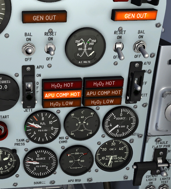
APU and BCS switches, indicators and gauges.
A dual-movement helium pressure gauge [45, fig. 5-1], common to both propellant feed systems, is on the right side of the instrument panel. The gauge, labeled "SOURCE", is calibrated in pounds per square inch (psi) and has two pointers, marked "1" and "2" for system identification.
The quantity of H2O2 available from the tanks is proportional to source (helium) pressure.
The pressure indicating system is powered by the 26-volt AC bus. Operating pressure will vary from 3600 down to 550 psi, depending upon the helium supply in the storage tank.
A dual-movement hydrogen peroxide pressure gauge [44, fig. 5-1], common to both propellant feed systems, is on the right side of the instrument panel. The gauge is labeled "H2O2" and is calibrated in pounds per square inch (psi). The pointers are marked "1" and "2" for system identification.
The gauge shows tank pressure in the hydrogen peroxide storage tanks, sensed by a pressure transmitter in each feed system. Normal operating pressure is approximately 550 psi.
The pressure indicating system is powered by the 26-volt AC bus.
A dual-pointer APU bearing temperature gage [43, fig. 5-1] is on the instrument panel. The gauge shows in degrees centigrade the temperature of No. 1 and No. 2 APU upper turbine bearings. The temperature indicating system is powered by the No. 1 primary ac bus. The gauge is calibrated from zero to 200 in increments of 20 degrees. The left pointer indicates No. 1 APU upper turbine bearing temperature; the right pointer, No. 2 APU upper turbine bearing temperature.
Each propellant feed system has a low-level caution light [31, fig. 5-1] that reads "H2O2 LOW" when on. The two amber, placard-type lights, on the right side of the instrument panel, are powered by the primary DC bus.
A pressure-differential switch in each system becomes energized, causing the related light to come on when the differential pressure between helium and hydrogen peroxide rises to approximately 35 psi. The light will come on at this instant, when approximately 20 percent of the hydrogen peroxide supply is left in the storage tank.
If either light comes on, extreme maneuvers should be avoided to prevent uncovering the inlet of the pickup tube in the tank, thus allowing helium to flow into the hydrogen peroxide line.
Note: During hydrogen peroxide transfer, the hydrogen peroxide low caution light will go out whenever the pressure differential drops below approximately 35 psi.
The No. 1 and No. 2 hydrogen peroxide overheat warning lights [28, fig. 5-1] are on the right side of the instrument panel. The red, placard-type lights are powered by the battery bus and read "H2O2 HOT" when on.
A thermoswitch at the base of each system hydrogen peroxide storage tank energizes the related light if the temperature of the contents of the tank rises to approximately 160° F. If either light comes on, the contents of the affected tank should be jettisoned. Concurrently, the related auxiliary power unit will automatically shut down.
Note: APU hydrogen peroxide tank overheating is not simulated in this software version.
Refer to "APU Speed Control Switches and Lights".
Refer to "Ballistic Control System".
See also:
Generator and APU Cooling and Pressurization