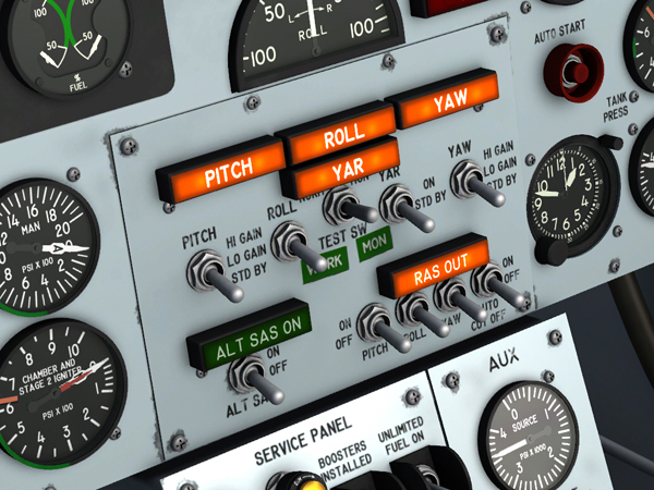
The SAS/ASAS/RAS panel.
True X-15-type SAS operation is not supported on the current simulation platforms. However, the X-15A-2 SE addon contains a modified SAS panel [48, fig. 5-1] with the basic autopilot controls for altitude hold, wing leveling, attitude hold and yaw damping modes.
This (fictitious) two-position switch [78, fig. 5-1], on the instrument panel left wing, engages the basic autopilot when positioned to SAS ON. To disengage the autopilot, the switch must be returned to OFF. The switch is powered by the primary DC bus.
This three-position switch [5, fig. 5-2], labeled "PITCH", controls the SAS pitch channel circuitry. All switch positions are maintained. The switch is powered by the primary DC bus.
With the switch at STD BY, the pitch channel is functioning, but the input signals to the servo cylinder control valves and hydraulic pressure to the servo cylinders are shut off. With the switch at LO GAIN or HI GAIN, pitch damping signals are applied to the pitch-roll servo cylinder control valves, which in turn permits hydraulic power to be applied to the servo cylinders. If both the pitch and roll function switches are at STD BY, the pitch-roll servo cylinders are centered and locked.
Basic autopilot: In the X-15A-2 SE addon, this switch engages the "ALTITUDE HOLD" autopilot mode when set to LO GAIN or HI GAIN. The "ALTITUDE HOLD" mode is disengaged when the switch is at STD BY.
This three-position switch [6, fig. 5-2], labeled "ROLL", is powered by the primary DC bus. It controls the SAS roll channel circuitry. All switch positions are maintained.
With the switch at STD BY, the roll channel is operating, but the input signals to the servo cylinder control valves and hydraulic pressure to the servo cylinders are shut off. With the switch at LO GAIN or HI GAIN, roll damping signals are applied to the pitch-roll servo cylinder control valves, which in turn permits hydraulic power to be applied to the servo cylinders. If both the pitch and roll function switches are at STD BY, the pitch-roll servo cylinders are centered and locked.
Basic autopilot: In the X-15A-2 SE addon, this switch engages the "WING LEVELER" autopilot mode when set to LO GAIN or HI GAIN. The "WING LEVELER" mode is disengaged when the switch is at STD BY.
The yaw function switch [9, fig. 5-2], labeled "YAW", has three maintained positions. The switch is powered by the primary DC bus.
With the switch at STD BY, the SAS yaw channel is operating, but the input signals to the servo cylinder control valve and hydraulic pressure to the servo cylinder are shut off and the yaw servo cylinder is centered and locked. With the switch at LO GAIN or HI GAIN, yaw damping signals are applied to the yaw servo cylinder control valve, which in turn permits hydraulic power to be applied to the servo cylinder. Shutoff or failure of hydraulic system No. 1 automatically causes the yaw servo cylinder to recenter and lock.
Basic autopilot: In the X-15A-2 SE addon, this switch engages the "YAW DAMPER" autopilot mode when set to LO GAIN or HI GAIN. The "YAW DAMPER" mode is disengaged when the switch is at STD BY.
This two-position switch [8, fig. 5-2], labeled "YAR", is powered by the primary DC bus. Both switch positions are maintained.
The switch controls the yaw signal input to the SAS roll control circuit. With the switch at STD BY, the "yar" signal circuit is inoperative. With the switch at ON while the roll function switch is at LO GAIN or HI GAIN, yaw signals are applied to the SAS roll control circuit. If the roll function switch is at STD BY or the roll control circuit does not function properly, yaw input to the SAS roll control circuit will neutralize roll and result in a "no roll" output.
Basic autopilot: In the X-15A-2 SE addon, this switch engages the "ATTITUDE HOLD" autopilot mode when set to LO GAIN or HI GAIN. The "ATTITUDE HOLD" mode is disengaged when the switch is at STD BY.
Four placard-type amber caution lights [1-4, fig. 5-2] indicate operating status of the SAS control circuits (and basic autopilot modes). The lights are powered by the primary DC bus and can be tested through the indicator, caution, and warning light test circuit.
There is one light for each of the pitch, roll, yaw, and "yar" channels. When the lights are ON, they read "PITCH", "ROLL", "YAW", and "YAR", respectively. The pitch, roll, and yaw lights are on when the pitch, roll, and yaw function switches (see above) are at STD BY (or the SAS power switch [78, fig. 5-1] is at OFF). When any one of these switches is at LO GAIN or HI GAIN and its control circuit is operating normally with the SAS power switch at ON, the associated caution light is out.
The "YAR" caution light shows only the "yar" function switch position. When the switch is at STD BY, the light is on. When the switch is at ON and the "yar" signal is available to the roll channels, the light is out.
Note: The SAS caution lights indicate the operating status of the basic autopilot functions of the X-15A-2 SE addon. When a light is on, the function is off. When the function is on, the light is out.
The three-position SAS test switch [7, fig. 5-2] is powered by the primary DC bus. It has momentary WORK and MON positions and a spring-loaded OFF position. While the pitch, roll, and yaw damping channels are engaged, singly or in combination, their working and monitor circuits can be tested during captive or free flight. Placing the switch at either WORK or MON opens the associated rate gyro ground circuits (working or monitor) and inserts a calibrated test voltage in series with the pick-offs. This voltage is added to the normal output of the gyro and unbalances the SAS channels beyond the expected trip level of the SAS malfunction detectors. If the SAS is functioning properly, the SAS caution lights for the channels being tested will blink, signaling malfunction circuit operation. After each set of circuits (working or monitoring) is tested, the SAS channels must be re-engaged.
Note: The SAS "yar" function switch [8, fig. 5-2] must be at STD BY and the SAS power switch [78, fig. 5-1] must be at SAS ON during the tests.
This two-position switch [77, fig. 5-1] on the instrument panel left wing, labeled "SAS DISENGAGE," is used to arm the SAS main gear cutout relay to shut off the SAS upon main gear touchdown. When the switch is moved to ARM, primary DC bus power is applied to the cutout relay to arm it. Moving the switch to the unmarked off position turns off power to the relay.
See also:
Stability Augmentation System (SAS)
Alternate Stability Augmentation System (ASAS)
Reaction Augmentation System (RAS)
Radio Communication and ADF Controls