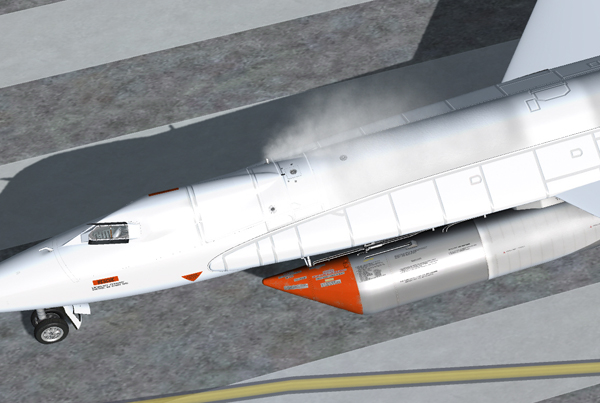
APU exhaust (Prepar3D® v2 screenshot).
On a real mission, the following procedures are done prior to countdown:
Starting the APUs
- APU switch No. 1 [17, fig. 5-1] – ON. As APU No. 1 comes up to speed, hydraulic pressure will increase and then stabilize at 3000 to 3500 psi.
- No. 1 generator switch [21, fig. 5-1] – Move No. 1 generator switch momentarily to RESET, then to ON.
- No. 1 generator out (amber) light [20, fig. 5-1] – Check OFF.
- APU switch No. 2 [30, fig. 5-1] – ON. As APU No. 2 comes up to speed, hydraulic pressure will increase and then stabilize at 3000 to 3500 psi.
- No. 2 generator switch [26, fig. 5-1] – Move No. 2 generator switch momentarily to RESET, then to ON.
- No. 2 generator out (amber) light [25, fig. 5-1] – Check OFF.
- Stable platform power switch [33, fig. 5-1] – INT (up position). Power is internal.
- Service panel external power switch [22, fig. 5-3] – OFF. Simulates disconnecting the external power from the external receptacle or from the B-52 carrier.
- Service panel external power (green) light [23, fig. 5-3] – Check OFF.
- Generator (AC) voltmeter [22, fig. 5-1] – Check (both pointers, 200 volts, internal). Power is internal.
- Hydraulic pressure gauge [13, fig. 5-1] – Check (both pointers, 3000 to 3500 psi).
- DC voltmeter selector switch [13, fig. 5-3] – Check BUS.
- DC voltmeter [12, fig. 5-3] – Check (28 volts).
- Ball nose power switch [6, fig. 5-3] – ON.
- Ball nose test button [7, fig. 5-3] – Check (normal).
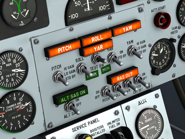
The SAS (basic autopilot) panel, on the main instrument panel.
SAS In-Flight Check
True X-15-type SAS operation is not supported on the current simulation platforms. However, the X-15A-2 SE addon contains a modified SAS panel [48, fig. 5-1] with the simulator's basic autopilot controls for altitude hold, wing leveling, attitude hold and yaw damping modes. Refer to "Stability Augmentation System (SAS)" for a complete description.
The addon avionics must be turned on for the basic autopilot to engage:
- Radio function selector switch [1, fig. 5-8] – Check ON, one step right to MAIN TR1, AUX. ADF. This also turns on the avionics.
Before launch, perform the following functional check of the stability augmentation (basic autopilot) system:
- SAS (basic autopilot) power switch [78, fig. 5-1] – SAS ON. This engages the basic autopilot.
- SAS yar function switch [8, fig. 5-2] – STD BY.
- SAS pitch, roll and yaw function switches [5, 6, 9, fig. 5-2] – LO GAIN. Check that the roll, pitch, and yaw caution (amber) lights [1-3, fig. 5-2] are out.
- SAS test switch [7, fig. 5-2] – Move SAS test switch to WORK (NORM) and check that the SAS pitch, roll and yaw caution (amber) lights blink; then release switch to OFF (CENTER).
- Pitch, roll and yaw function switches [5, 6, 9, fig. 5-2] – STD BY, then LO GAIN. When the switches are moved to STD BY, check that the caution (amber) lights [1-3, fig. 5-2] burn steadily; then move the switches to LO GAIN, and check that the caution lights go out.
- SAS test switch [7, fig. 5-2] – Move SAS test switch to MON and check that the SAS pitch, roll and yaw caution (amber) lights [1-3, fig. 5-2] blink; then release switch to OFF (CENTER).
- Pitch, roll and yaw function switches [5, 6, 9, fig. 5-2] – STD BY, then LO GAIN. When the switches are moved to STD BY, check that the caution (amber) lights [1-3, fig. 5-2] burn steadily; then move the switches to LO GAIN, and check that the caution lights go out.
- Pitch, roll and yaw function switches [5, 6, 9, fig. 5-2] – STD BY.
- SAS power switch [78, fig. 5-1] – OFF. This disengages the basic autopilot.
On a real mission, if a SAS malfunction is suspected during flight, the pilot can perform the preceding check at his discretion. The SAS check may be performed on any one function or a combination of pitch, roll, and yaw functions.
How to Engage the Basic Autopilot Modes
You can engage the simulator's basic autopilot modes at any time during flight using the switches on the modified SAS panel [48, fig. 5-1] in the virtual cockpit:
- Radio function selector switch [1, fig. 5-8] – Check ON, one step right to MAIN TR1, AUX. ADF (making sure the avionics is ON).
- SAS (basic autopilot) power switch [78, fig. 5-1] – SAS ON. This engages the basic autopilot.
- To engage the altitude hold mode: SAS pitch function switch [5, fig. 5-2] – LO GAIN or HI GAIN.
- To engage the wing leveler mode: SAS roll function switch [6, fig. 5-2] – LO GAIN or HI GAIN.
- To engage the attitude hold mode: SAS yar function switch [8, fig. 5-2] – LO GAIN or HI GAIN.
- To engage the yaw damping mode: SAS yaw function switch [9, fig. 5-2] – LO GAIN or HI GAIN.
- To disengage a single mode (or all modes): move the switch(es) to STD BY.
- To disengage the basic autopilot: SAS (basic autopilot) power switch [78, fig. 5-1] – OFF.
Known Issue
- We noticed that some of the simulator's basic autopilot functions such as "wing leveler" and "altitude hold", when engaged, induce unwanted oscillations at very high speed and altitude (instead of helping the pilot). Unfortunately, we have no other solution at this time but to recommend disengaging these functions when such behavior is encountered until a fix is found. This issue is resolved in Prepar3D® v4.
See also:
Auxiliary Power Units
Stability Augmentation System (SAS)