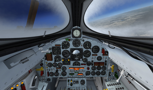
Fog on the windshield.
Operation of X-15 Liquid Nitrogen System
To operate the X-15 airplane liquid nitrogen system at prelaunch, proceed as follows:
- Ram-air lever [16, fig. 5-3] – CLOSED.
- Cabin source helium shutoff valve switch [11, fig. 5-9] – CLOSED.
- APU cooling switch [17, fig. 5-9] – NORMAL.
- Alternate cabin pressurization switch [27, fig. 5-9] – ON (down).
- Pressure-cooling lever [9, fig. 5-9] – ON.
- Vent suit heater switch [6, fig. 5-4] – HIGH or LOW.
- Pressure suit ventilation knob [5, fig. 5-4] – As required.
- X-15 LN2 supply switch (B-52) – Check CLOSE. Check with launch operator that switch is at CLOSE.
- Blower switches [10, fig. 5-9] – BLOWER & LN2.
- Windshield heater switches [36, fig. 5-1] – Check ON.
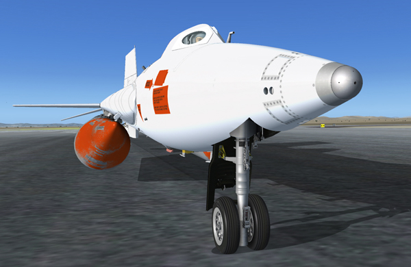
The NACA-Nortronics ball nose installed on the X-15A-2 SE.
Testing the Ball Nose
- Ball nose power switch [6, fig. 5-3] – ON.
- Ball nose test button [7, fig. 5-3] – Press (once).
Depressing the ball nose test button electrically simulates a predetermined airplane attitude. The ball nose should drive to a position that causes the angle-of-attack indicator to show about a 5-degree nose-down indication. The sideslip indicator will also read about a 15-degree sideslip to the left.
When the button is released, the ball nose should drive to the extreme position and appear as a 40-degree nose-up indication on the attitude indicator and a 30-degree sideslip to the right on the sideslip indicator. This reading should be maintained for 2 to 3 seconds, then the ball nose should resume normal operation, driving rapidly to indicate the actual angle of attack and sideslip of the airplane.
Preparing the External Tanks
- Fuel selector switch [8, fig. 5-6] – EXTERNAL.
- External tanks jettison auto-manual switch [3, fig. 5-6] – Check MANUAL.
- External tanks jettison buttons [5-6-7, fig. 5-6] – Check all (normal).
- Tank jettison circuit breakers [1-2, fig. 5-6] – ON/CLOSED (forward).
- External tanks jettison safe-arm switch [4, fig. 5-6] – ARM.
- Liquid oxygen top-off flapper valve - Check. Obtain confirmation from the launch operator that vaporous oxygen is no longer emitting from the liquid oxygen overboard vent of the B-52 pylon, or from the external tank vent valve. On a real mission, if liquid oxygen continues to emit from the pylon vent, indicating that either the internal or external tanks flapper valve is stuck open, the launch must be aborted.
Propellant Tank Pressurization
When the vent, pressurize, and jettison control lever [11, fig. 5-4] is moved to PRESSURIZE, ammonia and liquid oxygen tanks are pressurized and the propellants will be supplied to the engine turbopump. The hydrogen peroxide tank is also pressurized and H2O2 will be supplied to the turbopump cut-off valve.
- Vent, pressurize, and jettison control lever [11, fig. 5-4] – PRESSURIZE.
- Propellant tank pressure gauge [71, fig. 5-1] – Check ("L" pointer, 45 to 65 psi; "A" pointer, 45 to 65 psi).
- External tanks fuel flow indicator [4, fig. 5-1] – Check (both pointers, about 50% after initial pressurization).
- H2O2 tank and engine control line pressure gauge [55, fig. 5-1] – Check (“C” pointer, 575 to 615 psi; “T” pointer, 425 to 475 psi).
- Propellant pump inlet pressure gauge [72, fig. 5-1] – Check ("L" pointer, 45 to 65 psi; "A" pointer, 0 psi).
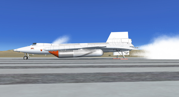
Jettison test (Prepar3D® v2 screenshot).
Propellant Jettison Tests
Propellant jettison tests will be conducted concurrently on all three systems (liquid oxygen, ammonia and hydrogen peroxide):
- Vent, pressurize, and jettison control lever [11, fig. 5-4] – JETTISON.
- Jettison stop switches [59, fig. 5-1] – JETT for about 3 seconds then STOP. In the spot plane exterior view, check for vapor emitting from the jettison ports, at the back of the X-15 aircraft.
- External tanks fuel flow indicator [31, fig. 4-1] – Check (both pointers, about 80% during jettison test).
- Vent, pressurize, and jettison control lever [5, fig. 4-7] – Return to PRESSURIZE.
Note: The liquid oxygen [5, fig. 3-2] and ammonia jettison ports [8, fig. 3-2] are the long tubes protruding at the back of the airplane's side fairings (each side of the engine compartment). The hydrogen peroxide jettison port [10, fig. 3-2] is located inside the lower speed brake compartment.
Proceed to "Launch" or read "Useful Information Before Launch".
See also:
Engine Controls
X-15A-2 Drop Tank System
Air Conditioning and Pressurization System
Propellant Supply System
Turbopump Propellant H2O2 System
Pitot Static System
Windshield Heating System