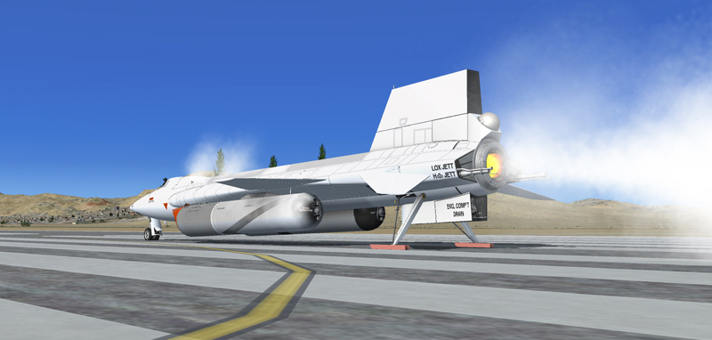
Igniter idle phase (Prepar3D® v2 screenshot).
Ballistic Control System and Reaction Augmentation System
Since some missions will involve flight at altitudes where control surfaces are ineffective and where ballistic control system operation will be required to maintain airplane attitude, the ballistic control system should be turned on before launch. The reaction augmentation system (RAS) should be turned on as soon as possible after engine burnout.
Note: The ballistic control system rockets were removed from the X-15A-2 with the full white ablative coating because the system was unnecessary for the high-speed flights.
Note: Current flight simulation platforms do not support ballistic control or reaction augmentation systems for rocket airplanes at this time. Consequently, the BCS and RAS switches on the X-15A-2 main panel do not perform any specific simulator function in this software version, other than being animated to simulate BCS and RAS-related procedures.
To turn on the ballistic control and reaction augmentation systems, proceed as follows:
- No. 1 ballistic control switch [18, fig. 5-1] – ON.
- No. 2 ballistic control switch [27, fig. 5-1] – ON.
- RAS pitch, roll and yaw function switches [13-15, fig. 5-2] – ON.
- RAS-out (amber) light [12, fig. 5-2] – OFF.
- RAS control indicator (amber) lights [10, fig. 5-4] – ON.
Because aerodynamic control surfaces become less and less effective above about 125,000 feet in the simulator as dynamic pressure decreases, we recommend flying the X-15A-2 addon below 200,000 feet. The simulator will still give you limited control at high altitudes, but flying will become more challenging. Note that the highest altitude attained by the real X-15A-2 rocket plane was 249,000 feet (August 3, 1966).
Preparation for Launch
- Oxygen selector and gauge (on the left side of the seat) [18, fig. 4-2] – X-15. Check gauge (3000 to 3200 psi).
- Eyelid handle [6, fig. 4-3] – AFT (eyelid closed).
- Propellant tank pressure gauge [71, fig. 5-1] – Check ("L" pointer, 45 to 65 psi; "A" pointer, 45 to 65 psi).
- External tanks fuel flow indicator [4, fig. 5-1] – Check (both pointers, about 50%).
- H2O2 tank and engine control line pressure gauge [55, fig. 5-1] – Check (“C” pointer, 575 to 615 psi; “T” pointer, 425 to 475 psi).
- Propellant pump inlet pressure gauge [72, fig. 5-1] – Check ("L" pointer, 45 to 65 psi; "A" pointer, 0 psi).
- DC voltmeter selector switch [13, fig. 5-3] – STRAIN GAGE.
- Check strain gauge (battery) power supply (24 volts) on DC voltmeter [12, fig. 5-3].
- DC voltmeter selector switch [13, fig. 5-3] – BUS.
- Flight controls – Check. On a real mission, the X-15 pilot moves all flight controls through allowable travel and receives verbal acknowledgment from the launch operator (in the carrier airplane) and the chase pilots that all control surfaces are operating properly.
- Engine precool switch [61, fig. 5-1] – PRECOOL.
- Engine prime switch [56, fig. 5-1] – PRIME. Move engine prime switch to PRIME for one second, then release it and check ignition ready light [2a, fig. 5-1] ON. The engine will continue to prime (at high flow rates) until the actual start stops the prime. On the real aircraft, about 30 seconds are required to prime the engine, with the prime valve at high-flow position. A continuous flow overboard of liquid oxygen and ammonia is observed at the back of the aircraft by the launch operator. The prime can be stopped at any time by placing the engine prime switch at STOP PRIME. This closes the liquid oxygen and ammonia tank main propellant valves and the H2O2 safety valve.
- Chamber and stage 2 igniter pressure gauge [50, fig. 5-1] – Check (both pointers, 0 psi).
- H2O2 source and purge pressure gauge [57, fig. 5-1] – Check (both internal and external tanks, 3000 to 3900 psi).
- H2O2 tank and engine control line pressure gauge [55, fig. 5-1] – Check (both pointers, 575 to 615 psi).
- Propellant pump inlet pressure gauge [72, fig. 5-1] – Check (both pointers, 45 to 65 psi).
- Turbopump idle button [54, fig. 5-1] – Push once. This will start the engine turbopump and hot exhaust gas will be emitted at the back of the aircraft [2, fig. 3-2].
- Propellant manifold pressure gauge [51, fig. 5-1] – Check (both pointers, 300 to 450 psi). The manifold pressure will increase during engine operation and will vary according to the movement of the throttle.
- Move the throttle on your joystick to its maximum (forward) position, then pull the throttle back to its minimum (aft) position. Make sure that the throttle on your joystick is set to its minimum position.
- Telemeter and radar switches [18, 14, fig. 5-3] – Check ON.
- Telemeter commutator motor switch [17, fig. 5-3] – Check ON.
- Communications – Check. Check communication with ground station, carrier pilot, and chase pilots.
Launch
- Ready-to-launch switch [52, fig. 5-1] – ON. Verbally check with carrier pilot and launch operator that the Ready-to-launch light is on.
- Operation of igniter idle is limited to 30 seconds. When 7 seconds remain of the normal igniter idle phase, the no-drop or 23-second (amber) caution light [2b, fig. 5-1] will come ON. With the no-drop or 23-second (amber) caution light on, the pilot must terminate the igniter idle phase – by moving the engine prime switch [56, fig. 5-1] to STOP PRIME – or continue on to the launch phase. On a real mission, the igniter idle phase must be terminated immediately if the idle-end caution light comes on, as damage to the engine chamber will occur because of insufficient cooling.
- Igniter idle switch [53, fig. 5-1] – IGNITER. When the igniter idle switch is placed to IGNITER, the ignition-ready light [2a, fig. 5-1] goes out for 2 seconds while the engine is purged with helium and the igniter spark plugs are energized. When this phase is completed, the ignition-ready light comes on again.
- Chamber and stage 2 igniter pressure gauge [50, fig. 5-1] – Check (small pointer, 150 psi in about 5 seconds, when stage 2 is ignited). Flames should be observed inside the XLR-99 rocket engine nozzle as stage 1 and stage 2 are ignited. The main chamber and stage 2 igniter pressure will increase during engine operation and will vary according to the movement of the throttle.
Ready to launch!
See also:
Aborted Launch
Engine Controls
Ballistic Control System
Reaction Augmentation System