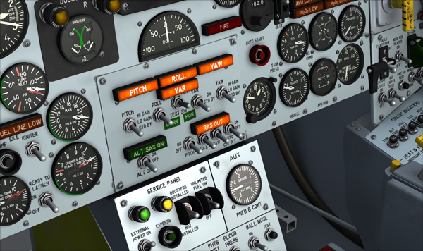
Buttons and switches on the main panel.
- Most 2-position switches can be turned ON or OFF with a simple left click with the mouse cursor positioned over the switch actuator. In addition, turning the mouse wheel up will turn the switch to ON, turning the mouse wheel down will turn the switch to OFF.
- 3-position switches can be turned to their UP position from their MIDDLE (or neutral) position by turning the mouse wheel up. Turning the mouse wheel down will move the switch actuator down one position at a time (UP, MID, DOWN). Turning the mouse wheel up will move the switch actuator up again one position at a time (DOWN, MID, UP). Single-clicking with the left mouse button has no effect on 3-position switches.
- Switch guards can be opened or closed with a simple left click with the mouse cursor positioned over the guard. In addition, turning the mouse wheel up will open the guard, turning the mouse wheel down will close the guard.
- Push-button switches and circuit breakers can be activated with a single left click on the center button/plunger.
- Most levers and handles can be dragged with the mouse to the desired position. Simply click on the handle with the left mouse button, drag the handle to the desired position, and release the mouse button.
- Control sticks cannot be dragged with the mouse because they are synchronized with the movements of your joystick or with the keyboard arrow keys (pitch and roll). Clicking the black handle activates the control stick. By default, the center stick and the right console stick are activated while the left ballistic control stick is deactivated.
- The rudder pedals are synchronized with the rotation movement of your joystick or your flight sim pedals.
- Knobs can be rotated with the mouse wheel. Turning the mouse wheel up will turn the knob to the right, turning the mouse wheel down will turn the knob to the left. Continuous rotation is possible on some knobs by left or right clicking with the mouse and leaving the mouse button depressed until the knob is set to the desired position.
- The radio frequency units can be changed by left or right clicking the radio channel selector knob [2-3, fig. 5-8]. The radio frequency decimals can be changed by turning the mouse wheel up or down while pointing the radio channel selector knob. Continuous rotation is possible by left or right clicking with the mouse and leaving the mouse button depressed until the knob is set to the desired position.
Important
- It sometimes occurs that the pilot's viewpoint is adjusted too far back and lays inside the pilot seat's backrest, rendering the switches unclickable. When this happens, simply move your viewpoint forward a little.
- Some switches must be activated in a logical, predetermined order or sequence to function. If not, the switch is simply disabled and will not respond to mouse clicks. If a switch refuses to operate normally, please revise the previous procedures and make sure that all the required steps have been performed in the correct order. These switches are:
- The external drop tanks option switch [26, fig. 5.3] on the service panel section of the center pedestal - can only be moved if the vent, pressurization, and jettison lever [11, fig. 5.4] on the left white control box is at VENT.
- The unlimited fuel option switch [27, fig. 5.3] on the service panel section of the center pedestal - cannot be moved when the engine master switch [63, fig. 5.1] on the main panel is at ON.
- The igniter-idle switch [53, fig. 5.1] on the main panel - cannot be moved if the engine turbopump is not running.
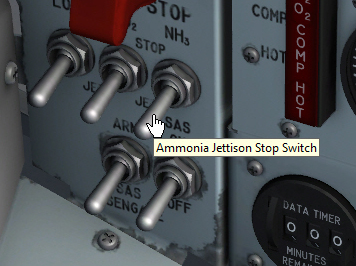
Tooltip over a switch in the virtual cockpit.
- Tooltips (small yellow rectangles with text that appear under the mouse pointer that contain the description and reading of the underlying device) are integrated in every clickable parts in the cockpit. When the mouse cursor becomes a hand and the tooltip is displayed, the device can usually be activated with the mouse. If the mouse cursor does not change but the tooltip appears, it means that the device cannot be clicked. However, the tooltip still contains useful information.
The tooltip always displays the correct reading of the underlying instrument even if power is not supplied to the instrument and the pointers are indicating zero (or the light is out). This is an indication of electrical power not being supplied to the instrument, or that the breaker affecting the instrument is pulled out, or that the instrument is defective. Also, the tooltip over a switch shows the state of that particular switch (ON/OFF, etc.) only if the switch has no markings on the instrument panel.
Note: If you can't see the tooltips in the virtual cockpit, make sure the "Show cockpit tooltips" option is selected in your simulator's display settings. Refer to "Compatibility, Performance and Settings".
See also:
How to Move the Pilot's Viewpoint in the Virtual Cockpit