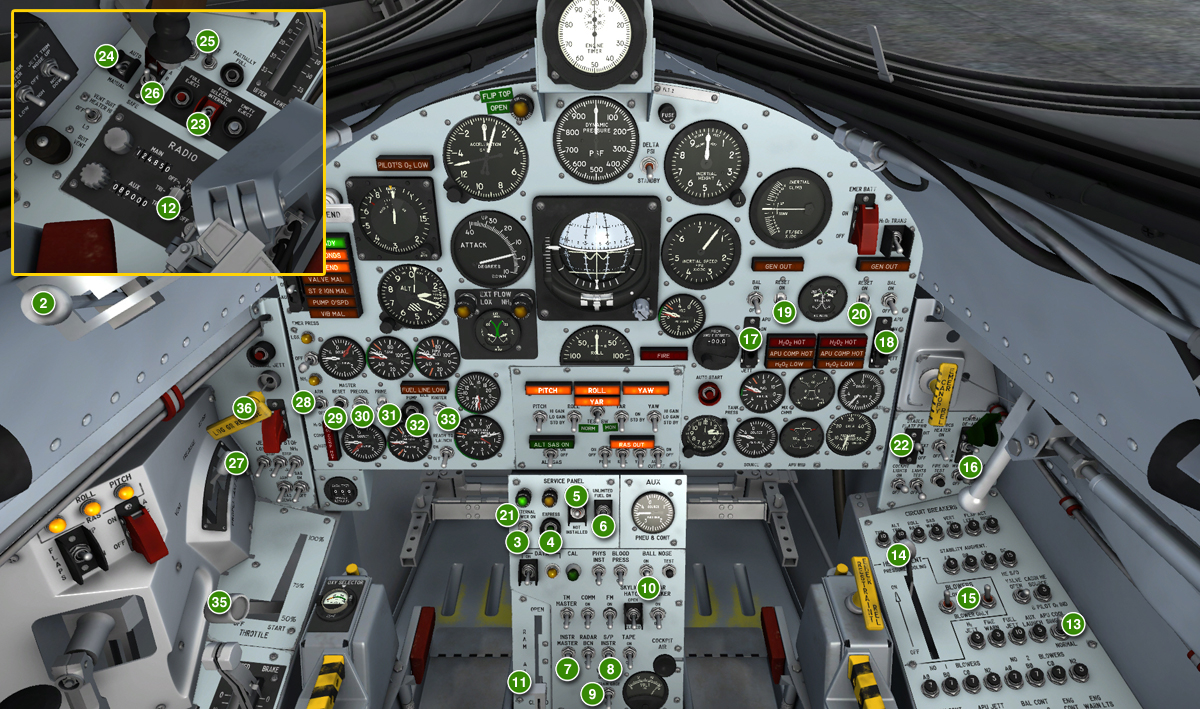
Quick-start procedures (in green circles). Steps 1 and 34 are not shown (parking brake set/released).
The following "quick-start" procedures can be followed to start the engine and fly the X-15A-2 SE without going through the complete check list and procedures presented in the previous section. We recommend that you use these procedures only if you are familiar with both your simulation platform and the X-15A-2 SE addon.
We assume that you have already started your simulation platform, created a flight and configured the simulator with the optimal settings for your system. We also assume that the engine is shut down and that there are no unwanted special visual effects around the X-15A-2 aircraft and that you are in the virtual cockpit view ("F9").
Make sure the parking brake is applied ("CTRL+." keys). You can also hide the center stick for a better access to the center pedestal controls by clicking the center stick leather boot [9, fig. 4-1].
Quick-Start Procedures
Note: Each step in the check list below is numbered in the image above (green circles). Steps 1 and 34 are not shown (parking brake applied/released).
- Parking brake – Check APPLIED ("CTRL+." keys).
- Eyelid handle [6, fig. 4-3] – AFT (eyelid closed).
- External power switch [22, fig. 5-3] – ON.
- Express fill button [24, fig. 5-3] – Push once.
- External tanks option switch [26, fig. 5-3] – Check INSTALLED.
- Unlimited fuel option switch [27, fig. 5-3] – ON.
- Instrumentation master power switch [15, fig. 5-3] – ON.
- Stable platform instrument power switch [10, fig. 5-3] – ON.
- DC voltmeter switch [13, fig. 5-3] – BUS.
- Ball nose power switch [6, fig. 5-3] – ON.
- Ram-air lever [16, fig. 5-3] - CLOSED.
- Radio function selector switch [1, fig. 5-8] – Turn ON, one step right to MAIN TR1, AUX. ADF.
- APU cooling switch [17, fig. 5-9] - NORMAL.
- Pressure-cooling lever [9, fig. 5-9] - ON.
- Blower switches [10, fig. 5-9] - BLOWER & LN2.
- Windshield heater switches [36, fig. 5-1] – ON.
- No. 1 APU switch [17, fig. 5-1] – ON.
- No. 2 APU switch [30, fig. 5-1] – ON.
- No. 1 generator switch [21, fig. 5-1] – ON.
- No. 2 generator switch [26, fig. 5-1] – ON.
- External power switch [22, fig. 5-3] – OFF.
- Stable platform switch [33, fig. 5-1] – INTERNAL (up position).
- Fuel selector switch [8, fig. 5-6] – Check EXTERNAL.
- External tanks jettison auto-manual switch [3, fig. 5-6] – Check MANUAL.
- Tank jettison circuit breakers [1-2, fig. 5-6] – ON/CLOSED (forward).
- External tanks jettison safe-arm switch [4, fig. 5-6] – ARM.
- Vent, pressurize, and jettison control lever [11, fig. 5-4] – PRESSURIZE. Wait 5 seconds.
- Engine master switch [63, fig. 5-1] – ARM.
- Engine turbopump reset switch [62, fig. 5-1] – PUSH once.
- Engine precool switch [61, fig. 5-1] – PRECOOL.
- Engine prime switch [56, fig. 5-1] – PRIME. Move engine prime switch to PRIME, then release it. Wait 5 seconds.
- Engine turbopump idle switch [54, fig. 5-1] – PUSH once. Wait 5 seconds.
- Engine igniter idle switch [53, fig. 5-1] – ON. Wait 10 seconds.
- Parking brake – RELEASED ("." key).
- Throttle [12, fig. 5-4] – START (click and then move inboard to about 75%). Throttle must be moved to START 50% by the time the idle-end (amber) caution light [2b, fig. 5-1] comes on.
- As soon as the aircraft is airborne, raise the landing gear by pushing the landing gear handle [65, fig. 5-1] on the left wing panel (or by pressing the "G" key on your keyboard or the appropriate button on your joystick).
See also:
Normal Procedures and Check List
Automatic Ignition Sequence Start Button
Emergency Procedures
The X-15 Experience