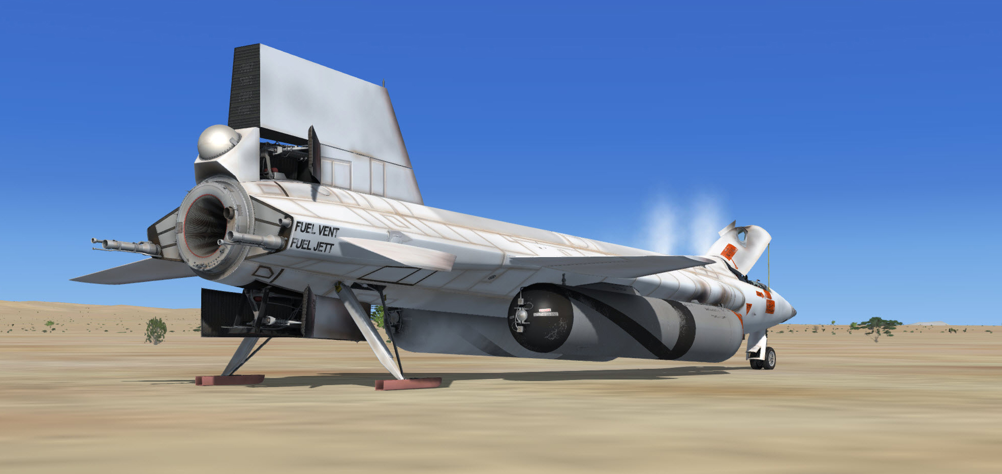
Last check list before leaving the airplane (Prepar3D® v4 screenshot).
On a real mission, before leaving the airplane, complete the required airplane form.
Verify the following cockpit control positions:
- Parking brake – Check APPLIED ("CTRL+." keys).
Left console, seat and wing panel:
- Trim control switch [1, fig. 5-4] – Check CENTER.
- Intercom switch [2, fig. 5-4] – Check OFF.
- Face mask heater switch [3, fig. 5-4] – OFF.
- Jettison trim switch [4, fig. 5-4] – Check OFF.
- Vent suit heater switch [6, fig. 5-4] – OFF.
- Pressure suit ventilation knob [4, fig. 5-4] – CLOSED.
- Radio function selector switch [1, fig. 5-8] – OFF.
- Tank jettison circuit breakers [1-2, fig. 5-6] – OFF/OPEN (aft).
- External tanks jettison auto-manual switch [3, fig. 5-6] – Check MANUAL.
- External tanks jettison safe-arm switch [4, fig. 5-6] – SAFE (guard down).
- External tanks jettison buttons [5-6-7, fig. 5-6] – Check all (normal).
- Fuel selector switch [8, fig. 5-6] – Check EXTERNAL.
- Speed brake handles [13-14, fig. 5-4] – Check AFT.
- Wing flap switch [9, fig. 5-4] – Check UP.
- Alternate SAS switch [16, fig. 5-4] – Check OFF (guard down).
- RAS (amber) indicator lights [10, fig. 5-4] – Check all OFF.
- Vent, pressurize, and jettison control lever [11, fig. 5-4] – Check VENT.
- Throttle [12, fig. 5-4] – Check OFF.
- SAS (land) disengage switch [77, fig. 5-1] – OFF.
- SAS (autopilot) power switch [78, fig. 5-1] – OFF.
- Jettison stop switches [59, fig. 5-1] – Check STOP.
- Auxiliary launch switch [60, fig. 5-1] – OFF (guard down).
- Ventral jettison button [67, fig. 5-1] – Check (normal).
- Landing gear handle [65, fig. 5-1] – Check OUT.
- Oxygen selector and gauge (on the left side of the seat) [18, fig. 4-2] – OFF.
Main instrument panel:
- Ignition-ready (green) light [2a, fig. 5-1] – Check OFF.
- 23-second caution (amber) light [2b, fig. 5-1] – Check OFF.
- Idle-end caution (amber) light [2c, fig. 5-1] – Check OFF.
- Valve malfunction caution (amber) light [2d, fig. 5-1] – Check OFF.
- Stage 2 igniter malfunction caution (amber) light [2e, fig. 5-1] – Check OFF.
- Turbopump overspeed caution (amber) light [2f, fig. 5-1] – Check OFF.
- Engine vibration malfunction caution (amber) light [2g, fig. 5-1] – Check OFF.
- Fire-warning (red) light [47, fig. 5-1] – Check OFF.
- Helium release selector switch [1, fig. 5-1] – Check OFF.
- Propellant emergency pressurization switch [68, fig. 5-1] – Check OFF.
- Ammonia tank pressure-low caution (amber) light [66, fig. 5-1] – Check OFF.
- Liquid oxygen tank pressure-low caution (amber) light [70, fig. 5-1] – Check OFF.
- Engine master switch [63, fig. 5-1] – Check OFF.
- Engine reset button [62, fig. 5-1] – Check (normal).
- Engine precool switch [61, fig. 5-1] – Check OFF.
- Engine prime switch [56, fig. 5-1] – Check STOP PRIME (DOWN).
- Turbopump idle button [54, fig. 5-1] – Check (normal).
- Igniter idle switch [53, fig. 5-1] – Check OFF.
- Fuel line low caution (amber) light [64, fig. 5-1] – Check OFF.
- H2O2 compartment-hot caution (amber) light [58, fig. 5-1] – Check OFF.
- Pilot's O2 low caution (amber) light [6, fig. 5-1] – Check OFF.
- External tanks jettison ready indicator (amber) lights [4, fig. 5-1] – Check both OFF.
- SAS pitch function switch [5, fig. 5-2] – Check STD BY.
- SAS roll function switch [6, fig. 5-2] – Check STD BY.
- SAS test switch [7, fig. 5-2] – Check OFF (middle).
- SAS yar function switch [8, fig. 5-2] – Check STD BY.
- SAS yaw function switch [9, fig. 5-2] – Check STD BY.
- SAS caution (amber) lights (four) [1-4, fig. 5-2] – Check all OFF.
- Alt SAS switch [11, fig. 5-2] – Check OFF.
- Alt SAS on (green) light [10, fig. 5-2] – Check OFF.
- RAS pitch function switch [13, fig. 5-2] – Check OFF.
- RAS roll function switch [14, fig. 5-2] – Check OFF.
- RAS yaw function switch [15, fig. 5-2] – Check OFF.
- RAS auto cutoff switch [16, fig. 5-2] – Check OFF.
- RAS out (amber) light [12, fig. 5-2] – Check OFF.
- Retractable pitot handle [80, fig. 5-1] – IN.
- Skylight hatch open (amber) light [73, fig. 5-1] – Check OFF.
- Automatic ignition sequence start button [76, fig. 5-1] – Check (normal).
- Ready-to-launch switch [52, fig. 5-1] – OFF.
- Engine timer [11, fig. 5-1] – Note time. RESET.
Main instrument panel (electrical, hydraulic, and cockpit):
- Emergency battery switch [23, fig. 5-1] – Check OFF (guard down).
- Hydrogen peroxide transfer switch [24, fig. 5-1] – Check OFF.
- No. 1 generator-out (amber) light [20, fig. 5-1] – Check OFF.
- No. 2 generator-out (amber) light [25, fig. 5-1] – Check OFF.
- No. 1 and No. 2 generator switches [21, 26, fig. 5-1] – Check OFF.
- APU No. 1 switch [17, fig. 5-1] – Check OFF.
- APU No. 1 warning and caution lights [28, 29, 31, fig. 5-1] – Check OFF.
- No. 1 ballistic control switch [18, fig. 5-1] – Check OFF.
- No. 2 ballistic control switch [27, fig. 5-1] – Check OFF.
- APU No. 2 warning and caution lights [28, 29, 31, fig. 5-1] – Check OFF.
- APU No. 2 switch [30, fig. 5-1] – Check OFF.
- Cabin pressure altimeter [41, fig. 5-1] – Check.
Center pedestal (service panel):
- External power switch [22, fig. 5-3] – OFF.
- External power (green) light [23, fig. 5-3] – Check OFF.
- External tank option switch [26, fig. 5-3] – ON.
- Unlimited fuel option switch [27, fig. 5-3] – ON or OFF (your choice).
Center pedestal (research instrumentation panel):
- Data switch [1, fig. 5-3] – OFF.
- Data (amber) light [2, fig. 5-3] – Check OFF.
- Calibrate button and (green) light [3, fig. 5-3] – Check (normal).
- Physiological instrumentation switch [4, fig. 5-3] – OFF.
- Blood pressure switch [5, fig. 5-3] – OFF.
- Ball nose power switch [6, fig. 5-3] – OFF.
- Ball nose test button [7, fig. 5-3] – Check (normal).
- Telemeter master power switch [18, fig. 5-3] – OFF.
- Telemeter commutator motor switch [17, fig. 5-3] – OFF.
- Telemeter FM switch [8, fig. 5-3] – OFF.
- Skylight hatch switch [19, fig. 5-3] – Check OFF (skylight hatch closed).
- Star tracker switch [20, fig. 5-3] – Check OFF.
- Instrumentation master power switch [15, fig. 5-3] – OFF.
- Radar beacon switch [14, fig. 5-3] – OFF.
- Stable platform instrument switch [10, fig. 5-3] – OFF.
- Tape recorder power switch [9, fig. 5-3] – OFF.
- Cockpit ram-air knob [11, fig. 5-3] – Check OFF (in)
- Ram-air lever [16, fig. 5-3] – CLOSED.
- DC voltmeter selector switch [13, fig. 5-3] – OFF.
Right console and wing panel:
- Canopy emergency release handle [32, fig. 5-1] – IN.
- Stable platform switch [33, fig. 5-1] – OFF.
- Nose ballistic rocket heater switch [34, fig. 5-1] – OFF.
- Ventral arming switch [35, fig. 5-1] – Check DE-ARM (guard down).
- Cockpit lighting switch [39, fig. 5-1] – OFF.
- Indicator, caution, and warning light test switch [38, fig. 5-1] – Check OFF.
- Fire-warning light test button [37, fig. 5-1] – Check (normal).
- Windshield heater switches (two) [36, fig. 5-1] – OFF.
- Canopy internal handle [1, fig. 5-5] – Check AFT and UNLOCKED (canopy open).
- Windshield antifogging (yellow) handle [2, fig. 4-3] – Check CLOSED (vertical) position.
- Windshield purge (gray) handle [3, fig. 4-3] – Check CLOSED (vertical) position.
- All breakers on the breaker panel – Check PUSHED IN (closed).
- Pressure-cooling lever [9, fig. 5-9] – OFF (aft position).
- Blower switches [10, fig. 5-9] – OFF (middle position).
- Cabin helium source shutoff valve switch [11, fig. 5-9] – OFF.
- APU nitrogen cooling switch [17, fig. 5-9] – OFF.
- Alternate cabin pressurization switch [27, fig. 5-9] – OFF.
Congratulations on your new high-speed (or high-altitude) record!