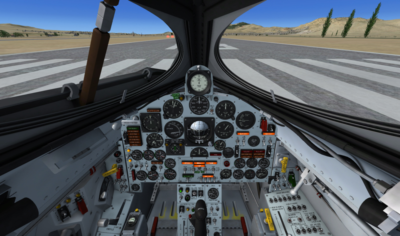
X-15A-2 SE virtual cockpit during preflight checks (Prepar3D® v2 screenshot).
Important
- It sometimes occurs that the pilot's viewpoint is adjusted too far back and lays inside the pilot seat's backrest, rendering the switches unclickable. When this happens, simply move your viewpoint forward a little.
- Some switches must be activated in a logical, predetermined order or sequence to function. If not, the switch is simply disabled and will not respond to mouse clicks. If a switch refuses to operate normally, please revise the previous procedures and make sure that all the required steps have been performed in the correct order. These switches are:
- The external drop tanks option switch [26, fig. 5.3] on the service panel section of the center pedestal - can only be moved if the vent, pressurization, and jettison lever [11, fig. 5.4] on the left white control box is at VENT.
- The unlimited fuel option switch [27, fig. 5.3] on the service panel section of the center pedestal - cannot be moved when the engine master switch [63, fig. 5.1] on the main panel is at ON.
- The igniter-idle switch [53, fig. 5.1] on the main panel - cannot be moved if the engine turbopump is not running.
Preflight Checks
For the following procedures, it is assumed that external power is supplied to the aircraft (external power switch [22, fig. 5-3] set to ON) and that the X-15 internal and external tanks are filled. Refer to "Servicing the Aircraft" for details.
Note: You can hide the center stick for a better access to the center pedestal controls by clicking the center stick boot [9, fig. 4-1].
- Parking brake (if released, takeoff only) – APPLIED ("CTRL+." keys).
Left console, seat and wing panel:
- Trim control switch [1, fig. 5-4] – CENTER.
- Intercom switch [2, fig. 5-4] – OFF.
- Face mask heater switch [3, fig. 5-4] – OFF.
- Jettison trim switch [4, fig. 5-4] – OFF.
- Vent suit heater switch [6, fig. 5-4] – OFF.
- Pressure suit ventilation knob [4, fig. 5-4] – CLOSED.
- Radio function selector switch [1, fig. 5-8] – OFF.
- Tank jettison circuit breakers [1-2, fig. 5-6] – OFF/OPEN (aft).
- External tanks jettison auto-manual switch [3, fig. 5-6] – MANUAL.
- External tanks jettison safe-arm switch [4, fig. 5-6] – SAFE (guard down).
- External tanks jettison buttons [5-6-7, fig. 5-6] – Check all (normal).
- Fuel selector switch [8, fig. 5-6] – EXTERNAL.
- Speed brake handles [13-14, fig. 5-4] – CLOSED (forward).
- Wing flap switch [9, fig. 5-4] – UP.
- Alternate SAS switch [16, fig. 5-4] – OFF (guard down).
- RAS (amber) indicator lights [10, fig. 5-4] – Check all OFF (RAS functions are off)..
- Vent, pressurize, and jettison control lever [11, fig. 5-4] – VENT. On a real mission, the vent valve on the internal ammonia tank is manually closed before flight to prevent losing ammonia during captive flight (when the X-15A-2 is attached to the B-52 carrier). When the vent, pressurize, and jettison control lever is placed in the PRESSURIZE or JETTISON position and then back to VENT, the ammonia vent valve will then be open.
- Throttle [12, fig. 5-4] – OFF.
- SAS (land) disengage switch [77, fig. 5-1] – OFF.
- SAS (autopilot) power switch [78, fig. 5-1] – OFF.
- Jettison stop switches [59, fig. 5-1] – STOP. Check that all three switches (LOX, H2O2, and NH3) are in the STOP position.
- Auxiliary launch switch [60, fig. 5-1] – OFF (guard down).
- Ventral jettison button [67, fig. 5-1] – Check (normal).
- Landing gear handle [65, fig. 5-1] – NORMAL for takeoff.
- Eyelid handle [6, fig. 4-3] – FORWARD (eyelid open).
- Oxygen selector and gauge (on the left side of the seat) [18, fig. 4-2] – B-52, check (3000-3200 psi).
Main instrument panel:
- Ignition-ready (green) light [2a, fig. 5-1] – Check OFF.
- 23-second caution (amber) light [2b, fig. 5-1] – Check OFF.
- Idle-end caution (amber) light [2c, fig. 5-1] – Check OFF.
- Valve malfunction caution (amber) light [2d, fig. 5-1] – Check OFF.
- Stage 2 igniter malfunction caution (amber) light [2e, fig. 5-1] – Check OFF.
- Turbopump overspeed caution (amber) light [2f, fig. 5-1] – Check OFF.
- Engine vibration malfunction caution (amber) light [2g, fig. 5-1] – Check OFF.
- Fire-warning (red) light [47, fig. 5-1] – Check OFF.
- Helium release selector switch [1, fig. 5-1] – OFF.
- Propellant emergency pressurization switch [68, fig. 5-1] – OFF.
- Ammonia tank pressure-low caution (amber) light [66, fig. 5-1] – ON (tank is not pressurized).
- Liquid oxygen tank pressure-low caution (amber) light [70, fig. 5-1] – ON (tank is not pressurized).
- Propellant (helium) source pressure gauge [69, fig. 5-1] – Check (both internal and external tanks, 3300 to 3700 psi).
- Engine master switch [63, fig. 5-1] – OFF.
- Engine reset button [62, fig. 5-1] – Check (normal).
- Engine precool switch [61, fig. 5-1] – OFF.
- Engine prime switch [56, fig. 5-1] – STOP PRIME (DOWN).
- Turbopump idle button [54, fig. 5-1] – Check (normal).
- Igniter idle switch [53, fig. 5-1] – OFF.
- Propellant tank pressure gauge [71, fig. 5-1] – Check (liquid oxygen or “L” pointer, 0 to 5 psi; ammonia or “A” pointer, 0 to 10 psi).
- Propellant pump inlet pressure gauge [72, fig. 5-1] – Check (both pointers, 0 to 10 psi).
- Fuel line low caution (amber) light [64, fig. 5-1] – Check OFF.
- H2O2 (helium) source and purge pressure gauge [57, fig. 5-1] – Check (both internal and external tanks, 3000 to 3700 psi).
- H2O2 tank and engine control line pressure gauge [55, fig. 5-1] – Check (“C” pointer, 575 to 615 psi; “T” pointer, 0 psi).
- Propellant manifold pressure gauge [51, fig. 5-1] – Check (both pointers, 0 to 10 psi).
- H2O2 compartment-hot caution (amber) light [58, fig. 5-1] – Check OFF.
- Chamber and stage 2 igniter pressure gauge [50, fig. 5-1] – Check (both pointers, 0 psi).
- Pilot's O2 low caution (amber) light [6, fig. 5-1] – Check OFF.
- External tanks jettison ready indicator (amber) lights [4, fig. 5-1] – Check both OFF.
- External tanks fuel flow indicator [4, fig. 5-1] – Check (both pointers, 0%).
- SAS pitch function switch [5, fig. 5-2] – STD BY.
- SAS roll function switch [6, fig. 5-2] – STD BY.
- SAS test switch [7, fig. 5-2] – Check OFF (middle).
- SAS yar function switch [8, fig. 5-2] – STD BY.
- SAS yaw function switch [9, fig. 5-2] – STD BY.
- SAS caution (amber) lights (four) [1-4, fig. 5-2] – Check all ON (SAS functions are off).
- Alt SAS switch [11, fig. 5-2] – OFF.
- Alt SAS on (green) light [10, fig. 5-2] – Check OFF.
- RAS pitch function switch [13, fig. 5-2] – OFF.
- RAS roll function switch [14, fig. 5-2] – OFF.
- RAS yaw function switch [15, fig. 5-2] – OFF.
- RAS auto cutoff switch [16, fig. 5-2] – OFF.
- RAS out (amber) light [12, fig. 5-2] – ON (RAS functions are off).
- Retractable pitot handle [80, fig. 5-1] – IN.
- Skylight hatch open (amber) light [73, fig. 5-1] – Check OFF.
- Automatic ignition sequence start button [76, fig. 5-1] – Check (normal).
- Ready-to-launch switch [52, fig. 5-1] – OFF.
- Engine timer [11, fig. 5-1] – RESET.
Main instrument panel (flight instruments):
- Accelerometer [8, fig. 5-1] – Reset and check.
- Altimeter [3, fig. 5-1] – Set.
- Attitude indicator [9, fig. 5-1] – Set.
- Side-slip selector (delta psi) switch [12, fig. 5-1] – STANDBY.
- Pitch angle set control [16, fig. 5-1] – +0.00.
Main instrument panel (electrical, hydraulic, and cockpit):
- Emergency battery switch [23, fig. 5-1] – OFF (guard down).
- Hydrogen peroxide transfer switch [24, fig. 5-1] – OFF.
- No. 1 generator-out (amber) light [20, fig. 5-1] – Check ON (generator not in operation).
- No. 2 generator-out (amber) light [25, fig. 5-1] – Check ON (generator not in operation).
- Generator (AC) voltmeter [22, fig. 5-1] – Check (both pointers, 200 volts, external).
- No. 1 and No. 2 generator switches [21, 26, fig. 5-1] – OFF.
- APU No. 1 switch [17, fig. 5-1] – OFF.
- APU No. 1 warning and caution lights [28, 29, 31, fig. 5-1] – Check OFF.
- No. 1 ballistic control switch [18, fig. 5-1] – OFF.
- No. 2 ballistic control switch [27, fig. 5-1] – OFF.
- APU No. 2 warning and caution lights [28, 29, 31, fig. 5-1] – Check OFF.
- APU No. 2 switch [30, fig. 5-1] – OFF.
- APU (helium) source pressure gauge [45, fig. 5-1] – Check (both pointers, 3300 to 3900 psi).
- APU H2O2 pressure gauge [44, fig. 5-1] – Check (both pointers, 0 psi).
- Hydraulic pressure gauge [13, fig. 5-1] – Check (both pointers, 0 psi).
- Clock [46, fig. 5-1] – Check and set.
- Mixing chamber temperature gauge [42, fig. 5-1] – Check (approx. ambient temperature).
- APU bearing temperature gauge [43, fig. 5-1] – Check (approx. ambient temperature).
- Cabin (helium) source pressure gauge [40, fig. 5-1] – Check (3300 to 3900 psi).
- Cabin pressure altimeter [41, fig. 5-1] – Check.
Center pedestal (service panel):
- External power switch [22, fig. 5-3] – ON.
- External power (green) light [23, fig. 5-3] – Check ON.
- External tank option switch [26, fig. 5-3] – ON.
- Unlimited fuel option switch [27, fig. 5-3] – ON or OFF (your choice).
Center pedestal (research instrumentation panel):
- Auxiliary pneumatic and control (helium) pressure gauge [21, fig. 5-3] – Check (3000 to 3700 psi).
- Data switch [1, fig. 5-3] – OFF.
- Data (amber) light [2, fig. 5-3] – Check OFF.
- Calibrate button and (green) light [3, fig. 5-3] – Check (normal).
- Physiological instrumentation switch [4, fig. 5-3] – OFF.
- Blood pressure switch [5, fig. 5-3] – OFF.
- Ball nose power switch [6, fig. 5-3] – OFF.
- Ball nose test button [7, fig. 5-3] – Check (normal).
- Telemeter master power switch [18, fig. 5-3] – OFF.
- Telemeter commutator motor switch [17, fig. 5-3] – OFF.
- Telemeter FM switch [8, fig. 5-3] – OFF.
- Skylight hatch switch [19, fig. 5-3] – OFF (skylight hatch closed).
- Star tracker switch [20, fig. 5-3] – OFF.
- Instrumentation master power switch [15, fig. 5-3] – OFF.
- Radar beacon switch [14, fig. 5-3] – OFF.
- Stable platform instrument switch [10, fig. 5-3] – OFF.
- Tape recorder power switch [9, fig. 5-3] – OFF.
- Cockpit ram-air knob [11, fig. 5-3] – OFF (in)
- Ram-air lever [16, fig. 5-3] – OPEN.
- DC voltmeter selector switch [13, fig. 5-3] – BUS or STRAIN GAGE (select for testing).
- DC voltmeter [12, fig. 5-3] – Check (28-volt bus, or 24-volt strain gauge/battery bus).
Right console and wing panel:
- Canopy emergency release handle [32, fig. 5-1] – IN.
- Stable platform switch [33, fig. 5-1] – OFF (guard in place).
- Nose ballistic rocket heater switch [34, fig. 5-1] – OFF.
- Ventral arming switch [35, fig. 5-1] – DE-ARM (guard down).
- Cockpit lighting switch [39, fig. 5-1] – OFF.
- Indicator, caution, and warning light test switch [38, fig. 5-1] – OFF.
- Fire-warning light test button [37, fig. 5-1] – Check (normal).
- Windshield heater switches (two) [36, fig. 5-1] – OFF.
- Canopy internal handle [1, fig. 5-5] – FORWARD and LOCKED (canopy closed).
- Windshield antifogging (yellow) handle [2, fig. 4-3] – CLOSED (vertical) position.
- Windshield purge (gray) handle [3, fig. 4-3] – CLOSED (vertical) position.
- All breakers on the breaker panel – PUSHED IN (closed).
- Pressure-cooling lever [9, fig. 5-9] – OFF (aft position).
- Blower switches [10, fig. 5-9] – OFF (middle position).
- Cabin helium source shutoff valve switch [11, fig. 5-9] – OFF.
- APU nitrogen cooling switch [17, fig. 5-9] – OFF.
- Alternate cabin pressurization switch [27, fig. 5-9] – OFF.
See also:
Servicing the aircraft